
Thevenin’s Theorem with solved problem

Thevenin’s theorem is used to solve the complex circuits consisting of several sources and impedances by converting them into a simple equivalent circuit called Thevenin’s equivalent circuit. Now let’s look at the statement.
Thevenin’s Theorem states that
“ Any linear bilateral circuit containing several voltage sources and impedance s can be replaced with an equivalent circuit consisting of single Thevenin’s voltage source in series with a Thevenin’s impedance connected across the load impedance“.
The Thevenin’s equivalent circuit has a single voltage source called Thevenin’s voltage source(V TH ), equivalent impedance called Thevenin’s equivalent impedance Z TH and a load impedance Z L .

In the above equivalent circuit, the Thevenin’s voltage V TH is nothing but an open-circuit voltage, which is obtained by removing the load impedance Z L . The Thevenin’s equivalent impedance Z TH is obtained by short-circuiting all the voltage sources and open circuiting all the current sources in the circuit.
Now, let us look at the step-by-step procedure to determine the V TH and Z TH in the above circuit.
Procedure to determine Thevenin’s equivalent circuit
Step 1 – determination of thevenin’s voltage.
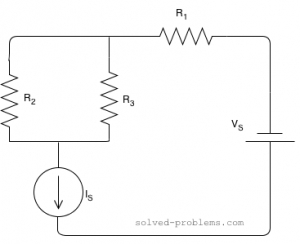
Remove the load impedance Z L in the above electric circuit, by open circuiting the terminal ab as shown in the below figure.

In this circuit, there exists a loop, through which the current I flows. Apply KVL to the loop and find the current I.
![\[I.Z_1 + I.Z_3 = V_s \]](https://www.electrically4u.com/wp-content/ql-cache/quicklatex.com-edfd349874ac1b2c8928719fc7a3ad9f_l3.png "Rendered by QuickLaTeX.com")
Solving the above equation, we will get the value of current. Then Thevenin’s voltage is obtained for the circuit as,
![\[V_{TH} = I.Z_3 \]](https://www.electrically4u.com/wp-content/ql-cache/quicklatex.com-559b5ae54c2976ca1da0d5b1fb492eb8_l3.png "Rendered by QuickLaTeX.com")
Step 2 – Determination of Thevenin’s Impedance
Since there is only one voltage source is available in the circuit, remove the voltage source and short circuit the terminals and remove the load impedance, as shown in the figure below.
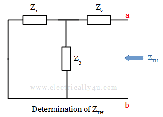
The Thevenin’s equivalent impedance is obtained from terminal ab using the formula,
![\[Z_{TH} = \frac{Z_1 . Z_3}{Z_1 + Z_3} + Z_2 \]](https://www.electrically4u.com/wp-content/ql-cache/quicklatex.com-df1f02e88d5c97c07d47f0f1c3d50598_l3.png "Rendered by QuickLaTeX.com")
Step 3 – Formation of Thevenin’s equivalent circuit
Using the obtained values of V TH and Z TH , the equivalent circuit is drawn as below. This circuit is called Thevenin’s equivalent circuit.

From this circuit, we can obtain the current flowing through the load, using the formula
![\[I_L = \frac{V_TH}{Z_TH + Z_L}\]](https://www.electrically4u.com/wp-content/ql-cache/quicklatex.com-9fdcaa9d7056a16e66d72a9281aec550_l3.png "Rendered by QuickLaTeX.com")
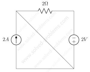
Solved Problem 1
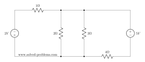
Solve the given circuit to find the current through 10 Ω using Thevenin’s Theorem.

First, let us consider 10 Ω as the load resistor.
(a) To find Thevenin’s voltage , Remove the load resistor(10 Ω) and the circuit is redrawn as below.

Now the circuit is open-circuited. From the drawn circuit, Thevenin’s voltage is calculated between a and b. Since no current flows through 2 Ω, V TH is equal to the voltage across 3 Ω resistor.
To find the voltage across the 3 Ω resistor, we need to know the current flowing through it.
The total resistance in the circuit, R = 1 Ω + 3 Ω = 4 Ω .
By Ohm’s law,
![\[I = \frac{V}{R} = \frac{9}{4} = 2.25 A\]](https://www.electrically4u.com/wp-content/ql-cache/quicklatex.com-6f2ef32b90273e1a09b1c53e6e3e18e6_l3.png "Rendered by QuickLaTeX.com")
Thus, the voltage across 3 Ω resistor(or Thevenin’s voltage V TH ) is given by,
![\[V_{ab} = V_{TH} = I * R = 2.25 * 3 = 6.75 V \]](https://www.electrically4u.com/wp-content/ql-cache/quicklatex.com-ab7c4779da3966f33c85b1aa347c8d1b_l3.png "Rendered by QuickLaTeX.com")
(b)To find Thevenin’s resistance, Remove the load resistor, short the voltage source and circuit is redrawn as below.

In this circuit, we can observe that the 2 Ω resistor is in series with the parallel combination of 1 Ω and 3 Ω resistors. Thus the equivalent value of resistance is obtained as,
![\[R_{TH} = 2 + \frac{1 * 3}{1 + 3} = 2.75 \Omega \]](https://www.electrically4u.com/wp-content/ql-cache/quicklatex.com-805dfaa6d0b7ee36288c67c8b83942b1_l3.png "Rendered by QuickLaTeX.com")
[ Learn how to find the equivalent resistance of resistor when they are connected in series and parallel. ]
(c)Thevenin’s Equivalent Circuit. It is drawn by connecting the Thevenin’s voltage V TH , Thevenin’s resistance R TH and load resistor in series, as shown below
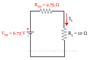
From this circuit, I L is the current flowing through the load of 10 Ω resistance.
![\[I_L = \frac{V_{TH}}{R_{TH} + R_L} = \frac{6.75}{2.75 + 10} = 0.529 A \]](https://www.electrically4u.com/wp-content/ql-cache/quicklatex.com-66855d697f245cf3b1d993057948f900_l3.png "Rendered by QuickLaTeX.com")
Please enable JavaScript
Solved Problem 2
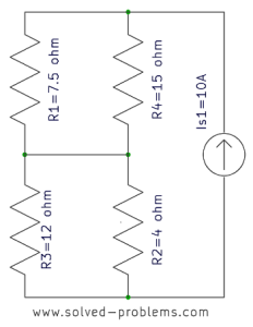
Solve the given circuit to find the current through 15 Ω using Thevenin’s Theorem.

In this problem, let us consider 15 Ω resistor as the load.
(a) To find Thevenin’s voltage , Remove the load resistor(15 Ω). Also when observing the circuit, it has 2A current source in parallel with the 5 Ω resistor.
By source transformation , let us convert this current source into its equivalent voltage source in series with 5 Ω resistor.

Now we have the following circuit, for which we have to find the Thevenin’s voltage V TH . You can observe a loop in this circuit. [ Learn how to solve a circuit using mesh analysis . ]

Let us apply Kirchoff’s Voltage Law to this loop and find the value of loop current.
Applying KVL, 20I + 5I +10 – 40 = 0
V TH = 10 + (5 * 1.2) = 16 v
(b)To find Thevenin’s resistance, Remove the load resistor, short the voltage source and the circuit is redrawn as below.

When you observe the circuit between points a and b, the 5 Ω resistor looks parallel to the 20 Ω resistor. Thus the equivalent value of resistance is obtained as,
![\[R_{TH} = \frac{5 * 20}{5 + 20} = 4 \Omega \]](https://www.electrically4u.com/wp-content/ql-cache/quicklatex.com-696ab6e7e4bee4537a9f65cf64e1bb14_l3.png "Rendered by QuickLaTeX.com")
Sharing is Caring

An Assistant Professor in the Department of Electrical and Electronics Engineering, Certified Energy Manager, Photoshop designer, a blogger and Founder of Electrically4u.
Related Posts

Leave a Reply Cancel reply
Your email address will not be published. Required fields are marked *
Save my name, email, and website in this browser for the next time I comment.
Good and helpful questions
Very Informative Topic
Very informative chapter .
sir how r u calculating vth in problem i am unable to understand sir i am having exam tmw can u help me out we u see this mail
I have added a video inside the above content, hope it might help you to understand.
Subscribe to Electrically4u..!
Enter your Email Address to get all our updates about new articles to your inbox.
- Electric Circuit
- Thevenin Theorem
Thevenin's Theorem
Most commonly, we use Ohm’s law, Kirchhoff’s law to solve complex electrical circuits, but we must also be aware that there are many circuit analysis theorems using which we can calculate the current and voltage at any given point in a circuit. Among the various circuit theorems, Thevenin’s theorem is most commonly used. In this article, let us learn about Thevenin’s theorem in detail.
Thevenin’s Theorem Explanation
Thevenin’s theorem states that it is possible to simplify any linear circuit, irrespective of how complex it is, to an equivalent circuit with a single voltage source and a series resistance.

A Thevenin equivalent circuit is shown in the image. In the image, we see that multiple resistive circuit elements are replaced by a single equivalent resistance R s and multiple energy sources by an equivalent voltage source V s .
Thevenin’s Theorem Example
Let us understand Thevenin’s Theorem with the help of an example.

Step 1: For the analysis of the above circuit using Thevenin’s theorem, firstly remove the load resistance at the centre, in this case, 40 Ω.
Step 2: Remove the voltage sources’ internal resistance by shorting all the voltage sources connected to the circuit, i.e. v = 0. If current sources are present in the circuit, then remove the internal resistance by open circuiting the sources. This step is done to have an ideal voltage source or an ideal current source for the analysis.
Step 3: Find the equivalent resistance. In the example, the equivalent resistance of the circuit is calculated as follows:

With the load resistance removed and the voltage sources shorted, the equivalent resistance of the circuit is calculated as follows:
The resistor 10 Ω is parallel to 20 Ω, therefore the equivalent resistance of the circuit is:
Step 4: Find the equivalent voltage.

To calculate the equivalent voltage, reconnect the voltage sources back into the circuit. V s = V AB , therefore the current flowing around the loop is calculated as follows:
The calculated current is common to both resistors, so the voltage drop across the resistors can be calculated as follows:
V AB = 20 – (20 Ω x 0.33 A) = 13.33 V
V AB = 10 + (10 Ω x 0.33 A) = 13.33 V
The voltage drop across both resistors is the same.
Step 5: Draw the Thevenin’s equivalent circuit. The Thevenin’s equivalent circuit consists of a series resistance of 6.67 Ω and a voltage source of 13.33 V.

The current flowing in the circuit is calculated using the formula below:
Thevenin’s theorem can be applied to both AC and DC circuits. But it should be noted that this method can only be applied to AC circuits consisting of linear elements like resistors, inductors, capacitors. Like Thevenin’s equivalent resistance, Thevenin’s equivalent impedance is obtained by replacing all voltage sources with their internal impedances.
Thevenin’s Theorem Solved Example
Find V TH , R TH and the load current I L flowing through and load voltage across the load resistor in the circuit below using Thevenin’s Theorem.

Step 1: Remove the 5 kΩ from the circuit.
Step 2: Measure the open-circuit voltage. This will give you the Thevenin’s voltage (V TH ).
Step 3: We calculate Thevenin’s voltage by determining the current that flows through 12 kΩ and 4 kΩ resistors.
As both the resistors are in series, the current that flows across them can be calculated as follows:
I = 48 V /( 12 kΩ + 4 kΩ) = 3 mA
The voltage across the 4 kΩ resistors can be calculated as follows:
3 mA x 4 kΩ = 12 V
As there is no current flowing through the 8 kΩ resistor, so there is no voltage drop across it and hence the voltage across the terminals AB is same as the voltage across the 4 kΩ resistor. Therefore, 12 V will appear across the AB terminals. Hence, the Thevenin’s voltage, V TH = 12 V.
Step 4: Short the voltage sources as shown in the figure below:

Step 5: Calculate the Thevenin’s Resistance
By measuring the open circuit resistance, we can measure Thevenin’s resistance.
We notice that the 8 kΩ resistor is in series with the parallel connection of 12 kΩ and 4 kΩ resistors. Therefore, the equivalent resistance or the Thevenin’s resistance is calculated as follows:
8kΩ + (4k Ω || 12kΩ)
R TH = 8 kΩ + 3 kΩ
R TH = 11 kΩ
Step 6: Now, connect the R TH in series with Voltage Source V TH and the load resistor as shown in the figure.

Step 7: For the last step, calculate the load voltage and load current using Ohm’s law as follows:
I L = V TH / (R TH + R L )
I L = 12 V / (11 kΩ + 5 kΩ) = 12 V/16 kΩ = 0.75 mA
The load voltage is determined as follows:
V L = 0.75 mA x 5 kΩ = 3.75 V
Thevenin Theorem Applications
Thevenin’s theorem is used in the analysis of power systems.
- Thevenin’s theorem is used in source modelling and resistance measurement using the Wheatstone bridge.
Thevenin Theorem Limitations
- Thevenin’s theorem is used only in the analysis of linear circuits.
- The power dissipation of the Thevenin equivalent is not identical to the power dissipation of the real system.
Frequently Asked Questions – FAQs
What is thevenin’s theorem.
Thevenin’s theorem states that it is possible to simplify any linear circuit, irrespective of how complex it is, to an equivalent circuit with a single voltage source and a series resistance.
What is Thevenin Voltage?
The open-circuit voltage that appears across the two terminals is the Thevenin voltage.
Where is Thevenin’s Theorem used?
Is thevenin’s theorem applicable to non-linear circuits.
No, Thevenin’s Theorem is not applicable to non-linear circuits.
Is Thevenin’s Theorem applicable to AC circuits?
Yes, Thevenin’s theorem applies to AC circuits.
Stay tuned to BYJU’S and Fall in Love with Learning !

Put your understanding of this concept to test by answering a few MCQs. Click ‘Start Quiz’ to begin!
Select the correct answer and click on the “Finish” button Check your score and answers at the end of the quiz
Visit BYJU’S for all Physics related queries and study materials
Your result is as below
Request OTP on Voice Call
Leave a Comment Cancel reply
Your Mobile number and Email id will not be published. Required fields are marked *
Post My Comment
- Share Share
Register with BYJU'S & Download Free PDFs
Register with byju's & watch live videos.

Electronic tutorials, Circuit diagram, MCQ, Projects etc

- Thevenin theorem
Thevenin theorem statement
Thevenin theorem definition, related posts:.
Thevenin’s theorem is very important in point of view to Simplify the Network and Reduction of Network complexity in any circuit. This is also a very important theorem for Engineering and diploma students in basic Electrical.
According to Thevenin’s theorem, any linear bilateral network irrespective of its complexities can be reduced into a Thevenin’s equivalent circuit having the thevenins’ open circuit voltage Vth in series with the Thevenin equivalent resistance Rth along with load resistance RL .
This theorem is named Thevenin’s theorem on the name of scientist Thevenin, he fist apply this theorem to the analysis of a circuit. By using this theorem we can reduce the complexity of any circuit network and can simplify if only two criteria are fulfilled 1st the network is linear and 2nd is bilateral. We see two elements in the simplified network 1st are Thevenin equivalent voltage Vth this is also called open-circuit voltage (Voc) , a series resistance Rth connected with this vth, this series resistance Rth is called Thevenin equivalent resistance. all of them are connected in series with a load resistance RL.
We can find the current IL which is flowing through the load resistance RL in any Thevenin equivalent circuit.
IL=Vth/Rth+RL
This identity is nothing But Ohm’s law {I=V/R} . Here RL is the load resistance which to say that finds the value in any question.
Now we go to steps that help us to solve the numerical question of Thevenin theorem. There are following steps required to solve the Thevenin’s theorem questions.
- Identify the load resistance value of RL
- Remove the load resistance and calculate the open circuit potential across the two open ends. This will be equivalent to Thevenin voltage Vth.- If I require the potential of load resistance then we need to remove the load resistance because after the removing of load resistance, there will create the Two points and at that point where we can find the potential difference, and this potential is called Thevenin equivalent Thevenin voltage. The reason behind removing the load resistance is to we need to find the voltage, If we need to find the current then I can short-circuit on that. So we remove the RL and Leave that point open and the potential difference between two points is our Vth or Voc(It is also said that open-circuit voltage).
- Again remove the load resistance and replace all active sources with their internal resistance and find Rth – If we find the equivalent resistance then there is no need of any active sources. We required only the internal resistance of those active sources.
- Calculate the equivalent resistance across the open ends. – This will we the Thevenin equivalent resistance Rth.
- Draw the Thevenin equivalent network.
- Calculate the Load current IL using this identity IL=Vth/Rth+RL
Thevenin’s theorem problems
Q. Find the value of current through 1Ω Resistor in the given circuit using Thevenin’s theorem.

Solution – First we have to remember that the IL Load current is current flow across the resistor which value says to find in question. So here IL is the current of the resistor of 1Ω and this is also here the load resistor RL. In question value across which resistor asks that is Load resistor RL.
According to step 1 find the value of RL- Here Value of RL = 1Ω
In 2nd step remove the Load resistance and calculate the open circuit Vth for the two open ends.
We can calculate the voltage at pint a and b using Kirchoff’s law (KCL AND KVL). so we use here KVL , first, we need a path between point a and b that completes a circuit between these. we need All elements to convert into voltage. So we have the shortest path between A and B through the 5Ω resistor. If we have the value of current across 5Ω resistor then I can calculate the voltage across 5Ω using Ohm’s law.

Applying KVL in All meshes.
10-10(I2-I1)-5I2=0 -15I2=10I1=-10 -15I2=-10-20=-30 -15I2=-30 I2=30/15=2A
The voltage across the 5Ω resistor is V=I*R=2*5=10Ω

and we consider point A and b is a voltage source of Vth, then the voltage of Vth is
Now we replace all active voltage and current sources with their internal resistance

If any circuit there is internal resistance as given below
[Voltage – if not given internal resistance of voltage source in any circuit means 0Ω=short circuit
Current – α(Infinite)= Open circuit)]
step 3 Remove again load resistance and replace all sources with their internal resistance, Then circuit will as below
Rth= 1/10+1/5 =3.33Ω
IL= Vth/Rth+RL=10/3.33+1
Q.2 Find the value of current across resistor 6Ω resistor using Thevenin’s Theorem.

solution –
The formula is IL= Vth/Rth+RL
RL is given in all circuits because the value of current across which resistor asked in the question, is Load resistor RL.
First, we remove the load resistance RL and make it open at that point.

After that replace all active sources with their internal resistance. Now, here no any internal resistance is given in sources.so, we assume that the internal resistance of all sources have 0Ω . Then sources are short circuits.

Q.3 Find the value of current across 5Ω resistor using the Thevenin’s Theorem

solution –
First, we remove the load resistor 5Ω from the circuit.

Replacing the sources with their internal resistance.

We find the current equation in all meshes using KVL
7I1-I2 =10 ——eq.1
-I1+6I2=0 ——eq 2.
by solving eq1 and 2 ——-eq.1
Applying KVL in mesh 3
-3(I3-I2)-Vth-20=0
-I3+3I1-Vth+20=0
3I2-Vth+20=0
I3=0 (because this mesh is open)
3(0.2434)+20=Vth
Vth=20.73170v

Rth = 2.857//3=1.4637
Draw the Thevenin equivalent circuit and calculate the value of current using ohm’s law

=3.20756A Ans.
Kirchoff’s law (kcl, kvl)
Norton’s theorem, how capacitor block dc current, logic gates, semiconductor p-n diode | p-n junction, related posts.

Automatic DC FAN controller circuit

220v 50W Low Power Inverter Circuit
 24")
What is NOT gate (Inverter)

Simple LED Flasher Circuit with 555 timer
Simple 2 led blinking flasher circuit.

Simple 5 LED Blinker/Flasher circuit

Best Low power Mic Amplifier circuit using LM386

Dual Power Supply Circuit
Leave a comment cancel reply.
Your email address will not be published. Required fields are marked *
- Switch skin
Home > Circuit Analysis > Thevenin’s Theorem. Step by Step Procedure with Solved Example
Thevenin’s Theorem. Step by Step Procedure with Solved Example
Thevenin’s Theorem in DC Circuit Analysis
A French engineer, M.L Thevenin , made one of these quantum leaps in 1893. Thevenin’s Theorem (also known as Helmholtz–Thévenin Theorem ) is not by itself an analysis tool, but the basis for a very useful method of simplifying active circuits and complex networks . This theorem is useful to quickly and easily solve complex linear circuits and networks, especially electric circuits and electronic networks.
Thevenin’s Theorem may be stated below:
Any linear electric network or a complex circuit with current and voltage sources can be replaced by an equivalent circuit containing a single independent voltage source V TH and a Series Resistance R TH .
- V TH = Thevenin’s Voltage
- R TH = Thevenin’s Resistance
Related Post: Norton’s Theorem. Easy Step by Step Procedure with Example (Pictorial Views)
Steps to Analyze an Electric Circuit using Thevenin’s Theorem
- Open the load resistor.
- Calculate / measure the open circuit voltage. This is the Thevenin Voltage (V TH ) .
- Open current sources and short voltage sources.
- Calculate /measure the Open Circuit Resistance. This is the Thevenin Resistance (R TH ) .
- Now, redraw the circuit with measured open circuit Voltage (V TH ) in Step (2) as voltage source and measured open circuit resistance (R TH ) in step (4) as a series resistance and connect the load resistor which we had removed in Step (1). This is the equivalent Thevenin circuit of that linear electric network or complex circuit which had to be simplified and analyzed by Thevenin’s Theorem . You have done it.
- Now find the Total current flowing through the load resistor by using the Ohm’s Law : I T = V TH / (R TH + R L ).
Related Post: SUPERMESH Circuit Analysis | Step by Step with Solved Example
Solved Example by Thevenin’s Theorem:

Calculate / measure the open circuit voltage. This is the Thevenin Voltage (V TH ) . Fig (3).
We have already removed the load resistor in figure 1, so the circuit became an open circuit as shown in fig 2. Now we have to calculate the Thevenin’s Voltage. Since 3mA current flows in both 12kΩ and 4kΩ resistors as this is a series circuit and current will not flow in the 8kΩ resistor as it is open.
This way, 12V (3mA x 4kΩ) will appear across the 4kΩ resistor . We also know that current is not flowing through the 8kΩ resistor as it is an open circuit, but the 8kΩ resistor is in parallel with 4k resistor . So the same voltage i.e. 12V will appear across the 8kΩ resistor as well as 4kΩ resistor. Therefore 12V will appear across the AB terminals. i.e,

Open current sources and short voltage sources as shown below. Fig (4)

Calculate / measure the open circuit resistance . This is the Thevenin Resistance (R TH )
We have removed the 48V DC source to zero as equivalent i.e. 48V DC source has been replaced with a short in step 3 (as shown in figure 3). We can see that 8kΩ resistor is in series with a parallel connection of 4kΩ resistor and 12k Ω resistor. i.e.:
8kΩ + (4k Ω || 12kΩ) ….. (|| = in parallel with)
R TH = 8kΩ + [(4kΩ x 12kΩ) / (4kΩ + 12kΩ)]
R TH = 8kΩ + 3kΩ
R TH = 11kΩ

Connect the R TH in series with Voltage Source V TH and re-connect the load resistor. This is shown in fig (6) i.e. Thevenin circuit with load resistor. This the Thevenin’s equivalent circuit .

Now apply the last step i.e Ohm’s law . Calculate the total load current and load voltage as shown in fig 6.
I L = V TH / (R TH + R L )
I L = 12V / (11kΩ + 5kΩ) → = 12/16kΩ
I L = 0.75mA
V L = I L x R L
V L = 0.75mA x 5kΩ
V L = 3.75V

Now compare this simple circuit with the original circuit shown in figure 1. Do you see how much easier it will be to measure and calculate the load current in complex circuit and network for different load resistors by Thevenin’s Theorem ? Yes and only yes.
Good to know: Both Thevenin’s and Norton’s theorems can be applied to both AC and DC circuits containing difference components such as resistors , inductors and capacitors etc. Keep in mind that the Thevenin’s voltage “V TH ” in AC circuit is expressed in complex number (polar form) whereas, the Thevenin’s resistance “R TH ” is stated in rectangular form.
- Maximum Power Transfer Theorem for AC & DC Circuits
- Kirchhoff’s Current & Voltage Law (KCL & KVL) | Solved Example
- Compensation Theorem – Proof, Explanation and Solved Examples
- Substitution Theorem – Step by Step Guide with Solved Example
- Millman’s Theorem – Analyzing AC & DC Circuits – Examples
- Superposition Theorem – Circuit Analysis with Solved Example
- Tellegen’s Theorem – Solved Examples & MATLAB Simulation
- SUPERNODE Circuit Analysis | Step by Step with Solved Example
- SUPERMESH Circuit Analysis | Step by Step with Solved Example
- Voltage Divider Rule (VDR) – Solved Examples for R, L and C Circuits
- Current Divider Rule (CDR) – Solved Examples for AC and DC Circuits
- Star to Delta & Delta to Star Conversion. Y-Δ Transformation
Electrical Technology
Related articles.

How to Size a Single Phase and Three Phase Transformer in kVA? Calculator

How to Calculate the Battery Charging Time & Battery Charging Current – Example

How To Calculate Your Electricity Bill. Electric Bill Calculator with Examples

How to Find the Proper Size of Wire & Cable: Metric & Imperial Systems

Automatic Street Light Control Circuit using LDR & Transistor BC 547

Emergency LED Light Circuit – DP-716 Rechargeable 30 LED’s Lights Schematic
108 comments.
thanks, good easy to understand.but the voltage source have more than one. how to do it.
It is simple example for ref & explanation purpose only…Wait for upcoming posts….Thanks
Surely when the load resistor is replaced the circuit changes and the 8k and 5k are in parallel with the 4k causing the cu
Surely when the load resistor is replaced the circuit changes and the 8k and 5k are in parallel with the 4k causing the current and voltage to change oops just figured it out the long way and the 5k gets 3.75 out of the 9.75 volts across that part of the circuit your way of showing thevenin is better thank you
Thanks for your kind words…
If the voltage source is more than one you calculate two components of Nortons current that is I’ and I”, add them to get the total Nortons current and repeat the procedure explained above.
Admin. You are doing great work. Your posts related to electricals are easy to learn. . . Keep updating. . .
Thanks for appreciation…
Thevenin's Theorem is not very intuitive for a newbie, good to have this nice easy to follow explanation.
simple and good steps for easy understanding
Good one for basic understanding of theorems :)<br />
How did u get 3mA?
I = V / R …<br />= 48V / (12kΩ + 4kΩ )<br />= 3mA <br /><br />So 3mA Current will flow in both 12kΩ and 4kΩ resistors as this is a series circuit because current will not flow in the 8kΩ resistor as it is open<br /><br />
If the rounded off value of 3mA is used to find Vth you get 12V. If the less rounded off value of 3.273mA is used we’d get 13V.
when the load terminals are open then all the current passes through only first circuit and the current is from v=i/r can be calculated
1st of all find req than by v=ir , i=v/r we can get the value of current
Thanku. <br />What happens when there is 2 voltage sources?
Use Kirchhoff law
i am proud that u can make this subject such intresting..<br /><br />hope many teachers of ur kind should be there..<br /><br />i am learning this during my job period ..if it was during my college it would have been a big deal for me..<br /><br />anyway thanks!!
hope many teachers of ur kind should be there..<br /><br />i am learning this during my job period ..if it was during my college it would have been a big deal for me..<br /><br />anyway thanks!!
Dhuurrrrrr!!
tq admin..mechanical stdent frm malaysia :)
Most welcome dear….
How can I find you in Facebook?
Here is the official Facebook Page of Electrical Technology .
step by step process is easy way for students to understand the problem
Great job there, sometimes is easy to understand through other source.
thank you sir…. this is really a helpful information..
thank u very much sir……
plesae provide telligan’s theorem
Thanks for your very informative post. I had a very bad going with this topic, but now I can assure keep my hands dirty on complex circuits related to this phenomenon by using your idea.
outstanding sir
it is very easy to understand the concept,but if more than one voltage sources are present then how will be the solution and procedure
It is too much easy
boss i love this your tutorials its the best i have ever seen you simplified the sturf to the last five star 4 u *****
best tutors site
Thank you…
sir this is awesome sir i had clarify my doubts succesfully
it is soo easy to understand
Thank you very much!!!
could you give another exercise with 2 suppliers? and show steps
Thumps up to yo tutorials,now I understand the theorem way better than I previously did.Thanx so Much
Thanks for appreciation….
why you solve 12 and 4 as parallel?
If you see in step 4, 8kΩ resistor is in series with a parallel connection of 4kΩ resistor and 12k Ω resistor. i.e. If you solve for the parallel connection of 4kΩ resistor and 12k Ω, It becomes in Series with 8kΩ.
In step 2, The Circuit is Open, Hence, Current will not flow in 8kΩ, Therefore, That’s Why it is in parallel with 4kΩ.
will you please add step by step procedure for dual loops that will help alot Thanx in advance
Great job. you make the determination of thevenin’s voltage is very very easy. Thank you…
I could not solve even a single problem .But this helped me a lot .Thank u
Glad it helps You….
Thanks…
can i get more relevant problems using thevinin’s theorem & may i know that thevinin’s theorem can use for AC supplied circuits.
Yes…. It can be used on both AC and DC Circuits,,, We will post about Thevinin’s theorem about AC Circuits in coming days… Thanks
Told how to solve thevinins them in ac by using kvl.
please inform more and more about electrical and electronics
sir I have a confusion when you calculate Rth because I dont think that Rth=8+4||12. But It should be Rth=12+4||8. Am I wrong Sir ?, if so then please guide me. Thanks Ankit
As mentioned above that We can see that 8kΩ resistor is in series with a parallel connection of 4kΩ resistor and 12k Ω resistor. i.e.: 8kΩ + (4k Ω || 12kΩ)
Saqib Javeed is Right…. Thanks
let me know if you want to know more… Thanks
simply superb
Thank you very much, this was the best explanation available on the internet
Thanks for appreciation …
Was very helpful…thanks a billion times ?
Most Welcome….
Awesome explanation. It’s very useful to us, Thank you!!
Most welcome… And thanks for appreciation….
have we already been provided with 3Am or you have solved it? if you have solved it how have you done it?? a ain’t sure if I have followed you on that one
It is not provided. In Step 2, You may see that this is an Open Circuit, I.e. Current will not flow in the 8kΩ. So the circuit of 48V, 4kΩ and 12kΩ becomes a series circuit. By using Ohms Law, (I = V/R), We found the value of current as 3mA. Thanks
what will be total R in the circuit if 4k shud the load resistance in revolving towards the source
You may just change the value of the resistance and solve again same as above…. No Difficulties…. :)
you said 8k resistor is parallel to 4k resistor in step 2.in step 4 you said 8k resistor is sereis to 4k.why?
Yes Dear…. If you see in step 4, 8kΩ resistor is in series with a parallel connection of 4kΩ resistor and 12k Ω resistor. i.e. If you solve for the parallel connection of 4kΩ resistor and 12k Ω, It becomes in Series with 8kΩ.
In step 2, The Circuit is Open, Hence, Current will not flow in 8kΩ, Therefore, That’s Why it is in parallel with 4kΩ. Thanks. let me know if you want to know more… Thanks
wow. thank you. now i understand. :)
thank you for this. but how about 3 sources using this theorem?
Please how was the 3mA current gotten ?
can you explain to me about how did you get 12V as it is 48V?
IT IS GOOD BUT I WILL LIKE IT IF IT SOLVED USING SMALL NUMBERS LIKE 3,4,2 TO MAKE IT LOOK MORE SIMPLER
Thevenin made simply. thanks dear.
A/C to my point of view, Its very simple and easy method for understanding..
Simplified example…great work
if I find current across 5 ohm resister there is a greater value then the total load current that is 0.75 can anyone answer
thanks for the example.
thank you dear
A really Understanding work!
Thanks for keeping the simplicity in the explination I thoroughly understood the conpect.
Thanks soooooo much, it really help me out.
Thank you so much to help me in easy way
And if there is an ammeter in parallel with the resistance, then what to do
Really good
If there are a voltage or current source between A & B terminals or in the place of load resistor, Then how can i solve this????????
VERY SIMPLY AND THOROUGHLY EXPLAINED THE CONCEPT OF THEVENINS THEOREM. PLEASE INCLUDE THE NOTES OF TWO POLE NETWORKS ALSO
Am happy for the steps of thevenins i cam now calculate but following the steps
sir please tell me….is this the right and only method to solve problems by thevenin’s theorem?
Yes! But you can analyze the same problem by different methods as well.
can you please tell me the different methods sir?
please respond quick!!
Very good explanation. I tend to solve complex circuits using Kirchoff’s laws…Are there particular cases when one method is favourably used instead of the other? ( I have not read all posts…maybe you have already gone into this)
how did u get 3mA
3mA current will flows in both 12kΩ and 4kΩ resistors as it is a series circuit because current will not flow in the 8kΩ resistor as it is open (Fig 2)
thankyou its help full. request.. how can I calculate if there are voltage source in the circuit?
thank u so much
Where does the load resistor come from? Can any load resistor be used?
Hi Admin If point A and point B are at 4kohm, how to get V(TH) and R(TH)? Thanks
Sir RL=5kom kese find ?
It is the given data in the first circuit (fig 1).
Sr i need more explanation on how you get 12v
Inspiring lessons, Thanks so much
Leave a Reply Cancel reply
Your email address will not be published. Required fields are marked *
Notify me of new posts by email.

Kindly permit ads on our free website.
Thevenin’s Theorem | Thevenin’s Equivalent Circuit
What is the thevenin’s theorem.
Thevenin’s Theorem states that any two-terminal linear network containing resistances and voltage sources and/or current sources may be replaced by single voltage source in series with a single resistance. The emf of the voltage source is the open circuit emf at the network terminals, and the series resistance is the thevenin’s equivalent resistance between the network terminals when sources are set to zero.
Suppose we are given an arbitrary circuit containing any or all of the following elements: resistors, voltage sources, current sources (the source can be dependent as well as independent). Let us identify a pair of nodes, say node a and b, such that the circuit can be partitioned into two parts as shown in figure 1.
Figure.1: Circuit partitioned into two parts
Furthermore, suppose that circuit A contains no dependent source that is dependent on a variable in circuit B and vice versa. Then, we can model circuit A by an appropriate independent voltage source, call it V oc that is connected in series with an appropriate resistance, call it R TH . This series combination of a voltage source and a resistance is called the Thevenin’s equivalent of circuit A. in other words, circuit A in figure 1 and the circuit in the shaded box in figure 2 have the same effect on circuit B. This result is known as Thevenin’s theorem and is one of the most useful and significant concepts in circuit theory.
Figure.2: Thevenin’s Equivalent Circuit
Circuit B (which is often called a load) may consist of many circuit elements, a single element (a load resistor), or no element.
- You May Also Read: Norton’s Theorem with Solved Examples
How to Find the Equivalent Voltage of a Thevenin Circuit?
To obtain the voltage V oc – called the open circuit voltage- remove circuit B from circuit A, and determine the voltage between node a and b ( where the + is at node a). This voltage, as shown in figure 3(a), is V oc .
Figure.3 (a): How to Find the Equivalent Voltage of a Thevenin Circuit
How to Find the Equivalent Resistance in Thevenin’s Theorem?
There are several ways to find the Thevenin’s equivalent resistance, which are given below: 1. To obtain the resistance R TH – called the Thevenin’s equivalent resistance of circuit A: i) Remove circuit B from circuit A. ii) Set all independent sources in circuit A to zero. (A zero voltage source is equivalent to a short circuit, and zero current source is equivalent to an open circuit). iii) Determine the resistance between nodes a and b- this is R TH – as shown in figure 3(b).
Figure.3 (b): Determination of Thevenin’s Equivalent Resistance R TH
2. Short-circuit the terminals a and b then find the short-circuit current I sc . The Thevenin equivalent resistance is given by
\[{{\text{R}}_{\text{th}}}\text{= }{{\text{V}}_{\text{oc}}}\text{/}{{\text{I}}_{\text{sc}}}\text{= }{{\text{V}}_{\text{th}}}\text{/}{{\text{I}}_{\text{sc}}}\]
3. When the source network has a ladder structure and contains no controlled (dependent) sources, R TH is easily found by series-parallel reduction of the dead network.
When the source network contains controlled sources , the Thevenin’s resistance can be found using the method represented by figure 4.
Figure.4: How to Find the Thevenin’s Equivalent Resistance
Here, the dead source network has been connected to an external test source. This test source may be any independent voltage or current source that establishes v o at the terminals. Since the dead network contains only resistors and controlled sources, and since R TH equals the equivalent resistance of the dead network, the equivalent resistance theorem tells us that
\[{{R}_{TH}}={{v}_{o}}/{{i}_{o}}\]
Thevenin’s Theorem Solved Example with Voltage Source
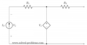
Find Thevenin equivalent circuit of the following network.
By applying nodal voltage method,
$\frac{{{V}_{1}}-25}{5}+\frac{{{V}_{1}}}{20}-3=0$
${{V}_{1}}=32~V$
${{V}_{th}}=32V$
To find short circuit current, we short-circuited terminals a and b as shown in the following figure:
Again using nodal voltage method ,
$\frac{{{V}_{2}}-25}{5}+\frac{{{V}_{2}}}{20}-3+\frac{{{V}_{2}}}{4}=0$
${{V}_{2}}=16~V$
${{I}_{sc}}=\frac{{{V}_{2}}}{4}=\frac{16}{4}=4A$
${{R}_{th}}=\frac{{{V}_{th}}}{{{I}_{sc}}}=\frac{32}{4}$
${{R}_{th}}=8~\Omega $
Now, we have following equivalent circuit:
Thevenin’s Theorem Solved Problem with Dependent Sources
Consider a circuit shown in the following figure. We will determine V th and R th across terminals a and b of the circuit.
Applying KCL at node 1:
\[\begin{matrix} \frac{{{V}_{1}}-5}{2000}+\frac{{{V}_{1}}}{6000}+\frac{{{V}_{1}}-{{V}_{2}}}{1000}=0 & \cdots & (1) \\\end{matrix}\]
Multiply (1) by 6000 yields
\[3{{V}_{1}}\text{- }15\text{ }+\text{ }{{V}_{1}}+\text{ }6{{V}_{1}}\text{ -}6{{V}_{2}}=\text{ }0\]
\[10{{V}_{1}}=\text{ }6{{V}_{2}}+\text{ }15\]
\[{{V}_{1}}=\text{ }0.6{{V}_{2}}+\text{ }1.5\]
Applying KCL at node 2:
\[\begin{matrix} \frac{{{V}_{2}}-{{V}_{1}}}{1000}+0.0005{{V}_{1}}+\frac{{{V}_{2}}}{10000}=0 & \cdots & (2) \\\end{matrix}\]
Multiply (2) by 10000 yields
\[10{{V}_{2}}\text{ -}10{{V}_{1}}+\text{ }5{{V}_{1}}+\text{ }{{V}_{2}}=\text{ }0\]
\[11{{V}_{2}}\text{ -}5{{V}_{1}}=\text{ }0\]
\[11{{V}_{2}}\text{- }5(0.6{{V}_{2}}+\text{ }1.5)\text{ }=\text{ }0\]
\[8{{V}_{2}}=\text{ }7.5\]
Finally we have
\[{{V}_{th}}=\text{ }{{V}_{oc}}=\text{ }{{V}_{2}}=\text{ }7.5/8\text{ }=\text{ }0.9375\text{ }V\]
Now, we have dependent source, so method 1 cannot be used for finding Thevenin’s Equivalent resistance Rth. Either Method 2 or Method 3 can be utilized here. We will prefer to employ second method. Terminals a and b are to be shorted as shown in the following figure and V 2 = 0.
\[\begin{matrix} \frac{{{V}_{1}}-5}{2000}+\frac{{{V}_{1}}}{6000}+\frac{{{V}_{1}}}{1000}=0 & \cdots & (3) \\\end{matrix}\]
Multiplying (3) by 6000 yields:
\[3{{V}_{1}}\text{- }15\text{ }+\text{ }{{V}_{1}}+\text{ }6{{V}_{1}}=\text{ }0\]
\[10{{V}_{1}}=\text{ }15\]
\[{{V}_{1}}=\text{ }1.5\text{ }V\to \text{ }v\text{ }=\text{ }{{V}_{1}}=\text{ }1.5\text{ }V\]
The current through R 3 (⟶) is given by
\[{{I}_{{{R}_{3}}}}=\text{ }{{V}_{1}}/{{R}_{3}}=~1.5\text{ }V/1k\Omega =\text{ }1.5mA\]
The current through VCCS (↓) is given by
\[{{I}_{VCCS}}=\text{ }0.0005{{V}_{1}}=~0.0005*1.5\text{ }A\text{ }=\text{ }0.75mA\]
Now, short-circuit current would be
\[{{I}_{sc}}=\text{ }{{I}_{{{R}_{3}}}}\text{ -}{{I}_{VCCS}}=\text{ }1.5mA\text{ -}0.75mA=\text{ }0.75mA\]
And Thevenin’s equivalent resistance is
\[{{R}_{th}}={{V}_{th}}/{{I}_{sc}}=\text{ }0.9675\text{ }V/0.75mA=\text{ }1.25\text{ }k\Omega \]
Thevenin’s Theorem Steps
Following steps are being used to determine Thevenin’s equivalent circuit.
- The portion of circuit considered as load is removed
- The open circuit voltage V oc is calculated at terminals.
- To calculate R th
- Short circuit all independent voltage sources.
- Open circuit all independent current sources.
- Draw equivalent circuit, connect the load and determine load current.
1 thought on “Thevenin’s Theorem | Thevenin’s Equivalent Circuit”
- Pingback: Norton Theorem and Norton Equivalent Circuit | Electrical Academia
Leave a Comment Cancel reply
You must be logged in to post a comment.

- school Campus Bookshelves
- menu_book Bookshelves
- perm_media Learning Objects
- login Login
- how_to_reg Request Instructor Account
- hub Instructor Commons
- Download Page (PDF)
- Download Full Book (PDF)
- Periodic Table
- Physics Constants
- Scientific Calculator
- Reference & Cite
- Tools expand_more
- Readability
selected template will load here
This action is not available.
5.4: Thévenin's and Norton's Theorems
- Last updated
- Save as PDF
- Page ID 25268

- James M. Fiore
- Mohawk Valley Community College
These theorems are related in that they allow complex linear networks to be simplified down to a single source with an associated internal impedance. They simplify analysis when checking a circuit with multiple possible loads.
Thévenin's Theorem
Thévenin's theorem is named after Léon Charles Thévenin. It states that:
\[\text{Any single port linear network can be reduced to a simple voltage source, } E_{th}, \text{ in series with an internal impedance } Z_{th}. \nonumber \]
It is important to note that a Thévenin equivalent is valid only at a particular frequency. If the system frequency is changed, the reactance and impedance values will change and the resulting \(E_{th}\) and \(Z_{th}\) values will be altered. Consequently, these equivalents are generally not appropriate for a circuit using multiple sources with differing frequencies 1 . A generic example of a Thévenin equivalent is shown in Figure \(\PageIndex{1}\).

The phrase “single port network” means that the original circuit is cut in such a way that only two connections exist to the remainder of the circuit. That remainder may be a single component or a large multi-component sub-circuit. \(E_{th}\) is the open circuit voltage at the port and \(Z_{th}\) is the impedance looking back into the port (i.e., the equivalent that now drives the remainder). As there are many ways to cut a typical circuit, there are many possible Thévenin equivalents. Consider the circuit shown in Figure \(\PageIndex{2}\).

Suppose we want to find the Thévenin equivalent that drives \(R_2\). We cut the circuit immediately to the left of \(R_2\). That is, The first step is to make the cut, removing the remainder of the circuit. In this case the remainder is just \(R_2\). We then determine the open circuit output voltage at the cut points (i.e., at the open port). This voltage is called the Thévenin voltage, \(E_{th}\). This is shown in Figure \(\PageIndex{3}\). In a circuit such as this, basic series-parallel analysis techniques may be used to find \(E_{th}\). In this circuit, due to the open, no current flows through the inductor, \(L\), and thus no voltage is developed across it. Therefore, \(E_{th}\) must equal the voltage developed across the capacitor, \(C\).

The second part is finding the Thévenin impedance, \(Z_{th}\). Beginning with the “cut” circuit, replace all sources with their ideal internal impedance (thus shorting voltage sources and opening current sources). From the perspective of the cut point, look back into the circuit and simplify to determine its equivalent impedance. This is shown in Figure \(\PageIndex{4}\). Looking in from where the cut was made (right side), we see that \(R_1\) and \(X_C\) are in parallel, and this combination is then in series with \(X_L\). Thus, \(Z_{th}\) is equal to \(jX_L + (R1 || −jX_C)\).

As noted earlier, the original circuit could be cut in a number of different ways. We might, for example, want to determine the Thévenin equivalent that drives \(C\) in the original circuit of Figure \(\PageIndex{2}\). The new port location appears in Figure \(\PageIndex{5}\).

Clearly, this will result in different values for both \(E_{th}\) and \(Z_{th}\). For example, \(Z_{th}\) is now \(R_1 || (R_2 + jX_L)\).
A common error is to find \(Z_{th}\) from the wrong perspective, namely, finding the impedance that the source drives. This is flatly incorrect. Remember, \(Z_{th}\) is found by looking into the port and simplifying whatever is seen from there. One way to remember this is that it is possible to create equivalents for multi-source circuits. In that instance, there isn't a single driving source, so finding its load impedance is nonsensical.
Measuring the Thévenin Equivalent in the Laboratory
In a laboratory situation, the Thévenin equivalent can be found quickly and efficiently with the proper tools. First, the circuit is “cut”, leaving just the portion to be Thévenized. The voltage at the cut points is measured with an oscilloscope. This is \(E_{th}\). All of the sources are then replaced with their internal impedance, ideally shorting voltage sources and opening current sources 2 . An LCR impedance meter can then be connected to the port to read \(Z_{th}\). If an impedance meter is not available, then the source(s) are left in place and an LCR substitution box is placed at the cut points. The box is adjusted so that the voltage across it is equal to half of \(E_{th}\). By the voltage divider rule, the value of the substitution box must be equal to \(Z_{th}\). In this case, the substitution box will yield either an inductance or capacitance value which can then be turned into a reactance given the frequency.
Example \(\PageIndex{1}\)
For the circuit of Figure \(\PageIndex{6}\), determine the Thévenin equivalent that drives the 300 \(\Omega\) resistor and find \(v_c\). Assume the source angle is \(0^{\circ}\).

First, let's find \(E_{th}\), the open circuit output voltage. We cut the circuit so that the 300 \(\Omega\) resistor is removed. Then we determine the voltage at the cut points. This circuit is shown in Figure \(\PageIndex{7}\).

There is no current flowing through the inductor due to the open. Therefore, the voltage across the inductor is zero. Consequently, \(E_{th}\) is the voltage across the capacitor, and that can be found with a voltage divider.
\[E_{th} = E \frac{X_C}{X_C +R_1} \nonumber \]
\[E_{th} = 10 \angle 0^{\circ} V \frac{− j 200\Omega}{− j 200\Omega +100 \Omega} \nonumber \]
\[E_{th} = 8.944\angle −26.6^{\circ} V \text{ or } 8 − j 4 V \nonumber \]
To find \(Z_{th}\), we replace the source with a short and then look back in from the cut points. The equivalent circuit is shown in Figure \(\PageIndex{8}\). The inductor is in series with the parallel combination of the resistor and capacitor.

\[Z_{left2} = \frac{R \times jX_C}{R − jX_C} \nonumber \]
\[Z_{left2} = \frac{100 \Omega \times (− j 200 \Omega )}{100 \Omega − j 200 \Omega} \nonumber \]
\[Z_{left2} = 89.44\angle −26.6^{\circ} \Omega \nonumber \]
\[Z_{th} = Z_{left2} + X_L \nonumber \]
\[Z_{th} = 89.44\angle −26.6 ^{\circ} \Omega + j 50\Omega \nonumber \]
\[Z_{th} = 80.62\angle 7.12^{\circ} \Omega or 80 +j 10\Omega \nonumber \]
The completed equivalent is shown in Figure \(\PageIndex{9}\).

The voltage across the 300 \(\Omega\) resistor can be found directly:
\[v_{R2} = E_{th} \frac{R_2}{Z_{th} + R_2} \nonumber \]
\[v_{R2} = 8 − j 4 V \frac{300\Omega}{80+j 10\Omega +300\Omega} \nonumber \]
\[v_{R2} = 7.06\angle −28.1^{\circ} V \nonumber \]
This value can be verified by following a standard series-parallel simplification. For example, the impedance of the three rightmost components \((181.4\angle −53.97^{\circ} \Omega )\) forms a voltage divider with the 100 \(\Omega\) resistor and the 10 volt source. This leads to \(v_b\) \((7.156\angle −18.61^{\circ}\) volts ). A second divider can then be used between \(v_b\), the inductor and the 300 \(\Omega\) resistor to find \(v_c\), which is \(7.06\angle −28.1^{\circ}\) volts as expected. The big advantage of using the Thévenin equivalent is that we can easily find \(v_c\) for any other value of load because we need only analyze the simpler equivalent circuit rather than the original.
Thévenin's theorem can also be used on multi-source circuits. The technique for finding \(Z_{th}\) does not change, however, finding \(E_{th}\) is a little more involved, as illustrated in the next example.
Example \(\PageIndex{2}\)
Find \(v_b\) for the circuit of Figure \(\PageIndex{10}\) using Thévenin's theorem.

This circuit is similar to the one used in Example 5.3.2 (Figure 5.3.5). The difference here is that the second source uses the same frequency as the first source. The reactance values are:
\[X_L = j314.2 \Omega \nonumber \]
\[X_C = −j212.2 \Omega \nonumber \]
The voltage across the 2 k\(\Omega\) is \(v_b\), so we'll treat that resistor as the load in order to define the equivalent circuit. This is redrawn in Figure \(\PageIndex{11}\).

To find \(Z_{th}\), we short the two sources. We're left with the inductor and capacitor in parallel. If this is confusing, remember that we are looking from node \(b\) to ground (the cut points), so they are not in series. That is, if a sensing current entered at node \(b\), it could split left and right, indicating parallel paths, not a series connection.
\[Z_{th} = \frac{− jX_C \times jX_L}{− jX_C +jX_L} \nonumber \]
\[Z_{th} = \frac{− j 212.2\Omega \times j 314.2 \Omega}{− j 212.2 \Omega + j 314.2 \Omega} \nonumber \]
\[Z_{th} = − j 653.7\Omega \nonumber \]
We have a few options to find \(E_{th}\). Superposition could be used, each circuit requiring a voltage divider. Alternately, the equivalent is basically a series loop as far as finding \(v_b\) is concerned. Thus, we could find the voltage across the inductor and subtract that from the left source (assuming a reference current direction of clockwise). Finding the inductor voltage requires either a voltage divider or finding the current. Neither approach is considerably less work than the other, and it's probably a good idea to get in a little more practice using superposition, so...
Considering the left source, we short the right source and find \(v_b\).
\[v_{bR} = E_1 \frac{X_C}{X_C +X_L} \nonumber \]
\[v_{bR} = 10 \angle 0^{\circ} V \frac{−j 212.2\Omega}{− j 212.2\Omega +j 314.2 \Omega} \nonumber \]
\[v_{bR} = 20.84\angle 180 ^{\circ} V \text{ or } −20.84\angle 0^{\circ} V \nonumber \]
For the right source, we short the left source and find \(v_b\). Then we add the two contributions to find the final voltage. Note that both sources will produce a reference polarity of + to − from top to bottom.
\[v_{bL} = E_2 \frac{X_C}{X_C + X_L} \nonumber \]
\[v_{bL} = 2\angle 0^{\circ} V \frac{j 314.2\Omega}{− j 212.2 \Omega +j 314.2 \Omega} \nonumber \]
\[v_{bL} = 6.16\angle 0^{\circ} V \nonumber \]
The sum of the two is \(−20.84\angle 0^{\circ} + 6.16\angle 0^{\circ}\), or \(14.68\angle 180^{\circ}\) volts. The Thévenin equivalent is a source of \(14.68\angle 180^{\circ}\) volts in series with an impedance of \(−j653.7 \Omega \).
To find the voltage across the 2 k\(\Omega\) resistor, we apply it to the equivalent circuit and solve.
\[v_b = E_{th} \frac{R}{R +Z_{th}} \nonumber \]
\[v_b = 14.68\angle 180 ^{\circ} V \frac{2 k\Omega}{ 2k \Omega +(− j 653.7\Omega )} \nonumber \]
\[v_b = 13.95\angle −161.9^{\circ} V \nonumber \]
Computer Simulation
To verify the results of the preceding example, the circuit of Figure \(\PageIndex{10}\) is captured in a simulator, as shown in Figure \(\PageIndex{12}\).

Next, a transient analysis is run, plotting the voltage at node 2, which corresponds to \(v_b\) in the original circuit. The result is shown in Figure \(\PageIndex{13}\). The plot is delayed by 0.1 seconds in order to get past the initial turn-on transient.

Both the amplitude and phase of the simulation waveform match the computed results.
Norton's Theorem
Norton's theorem is named after Edward Lawry Norton. It is the current source version of Thévenin's theorem. In other words, complex networks can be reduced to a single current source with a parallel internal impedance. Formally, Norton's theorem states:
\[\text{Any single port linear network can be reduced to a simple voltage source, } I_n, \text{ in parallel with an internal impedance } Z_n. \nonumber \]
The process of finding a Norton equivalent is very similar to finding a Thévenin equivalent. First, the Norton impedance is the same as the Thévenin impedance. Second, instead of finding the open circuit output voltage, the short circuit output current is found. This is the Norton current. Due to the equivalence afforded by source conversions, if a Thévenin equivalent for a network can be created, then it must be possible to create a Norton equivalent. Indeed, if a Thévenin equivalent is found, a source conversion can be performed on it to yield the Norton equivalent.
Example \(\PageIndex{3}\)
Let's reexamine Example \(\PageIndex{1}\), this time creating a Norton equivalent circuit. For convenience, the original circuit of Figure \(\PageIndex{6}\) is repeated in Figure \(\PageIndex{14}\). Once again, the goal will be to determine the equivalent that drives the 300 \(\Omega\) resistor and to find vc.

As noted, the Norton impedance, \(Z_n\), is the same as \(Z_{th}\). That was \(80 + j10 \Omega \). The Norton current, \(I_n\), is the short-circuit current through the cut points. We can think of this as replacing the load resistor with an ammeter. This is the same as the current through the inductor. In this situation, the capacitor and inductor are in parallel and yield an impedance of \(j66.67 \Omega \). Thus, the source current is:
\[i_{source} = \frac{E}{R +Z_{LC}} \nonumber \]
\[i_{source} = \frac{10\angle 0^{\circ}}{100\Omega +j 66.67\Omega} \nonumber \]
\[i_{source} = 83.2E-3\angle −33.7^{\circ} A \nonumber \]
This splits between the capacitor and inductor. Using the current divider rule we find:
\[i_n = i_{inductor} = I_{source} \frac{X_C}{X_C+X_L} \nonumber \]
\[i_n = 83.2 \angle −33.7^{\circ} A \frac{− j 200\Omega}{− j 200 \Omega +j 50\Omega} \nonumber \]
\[i_n = 0.1109\angle −33.7 ^{\circ} A \nonumber \]
A source conversion can be applied to verify this value. The resulting voltage source is \(8 − j4\) volts, precisely the value of the Thévenin equivalent.
Ultimately, deciding between using the Thévenin or Norton equivalents is a matter of personal taste and convenience. They work equally well.
1 It is possible that an equivalent can be valid across a specified range of frequencies, but it will not hold for all frequencies.
2 A typical laboratory signal generator has a 50 \(\Omega\) internal impedance, and using this value would be more accurate than just replacing the source with a shorting wire.

Thevenin theorem with solved problems
What is thevenin's theorem, thevenin theorem statements.

Thevenin's equivalent circuit

Solved problems by Thevenin's Theorem

- Share on Facebook
- Share on Twitter
Contact Form

Solved Problems
A Source of Free Solved Problems
Electrical Circuits
Resistive circuits, power and energy.
Thevenin’s and Norton’s Theorems/Equivalent
Voltage/Current Division
Circuit Reduction
Superposition
Mesh Analysis

Nodal Analysis

IMAGES
VIDEO
COMMENTS
11 1 1 2. 1. You seem to be trying to solve this as one problem. I would split it in 2 simple ones: 1) 9V + 150 ohm + 150 ohm and 2) 3 V + 100 ohm. Now make Thevenin equivalent for each. What do you get ? for 1 you get 300 ohms in parallel with a current source and for 2 something similar.
Solved Problem 2. Solve the given circuit to find the current through 15 Ω using Thevenin's Theorem. In this problem, let us consider 15 Ω resistor as the load. (a) To find Thevenin's voltage, Remove the load resistor (15 Ω). Also when observing the circuit, it has 2A current source in parallel with the 5 Ω resistor.
Thevenin's Theorem Example. Let us understand Thevenin's Theorem with the help of an example. Example: Step 1: For the analysis of the above circuit using Thevenin's theorem, firstly remove the load resistance at the centre, in this case, 40 Ω. Step 2: Remove the voltage sources' internal resistance by shorting all the voltage sources connected to the circuit, i.e. v = 0.
Example 2. Q.2 Find the value of current across resistor 6Ω resistor using Thevenin's Theorem. solution -. The formula is IL= Vth/Rth+RL. RL is given in all circuits because the value of current across which resistor asked in the question, is Load resistor RL. so Rl=6Ω.
Solved Example by Thevenin's Theorem: Example: Find VTH, RTH and the load current IL flowing through and load voltage across the load resistor in fig (1) by using Thevenin's Theorem. Solution:-. STEP 1. Open the 5kΩ load resistor (Fig 2). STEP 2. Calculate / measure the open circuit voltage. This is the Thevenin Voltage (VTH).
Problem: Let's find the Thevenin's equivalent circuit for the above circuit.. Solution. In the above circuit, we have a voltage source (32V) and another current source (2A). Step 1: Find Thevenin's resistance. While calculating the thevenin's equivalent resistance, all voltage sources must be turned off, meaning it acts like a short circuit and all current sources act like an open ...
Thevenins equivalent circuit is shown in figure (d) Example 2: Find the current flowing through 5Ω 5 Ω resistor of the circuit shown here. By using Thevenin's Theorem. Solution 2: Convert the 4A current source in the circuit into an equivalent voltage source as shown in figure (a) Fig: Solving the circuit.
Thévenin's theorem, named after Léon Charles Thévenin, is a powerful analysis tool. For DC, it states: Any single port linear network can be reduced to a simple voltage source, Eth, in series with an internal resistance, Rth. Figure 6.4.1 : Thévenin equivalent circuit. An example is shown in Figure 6.4.1 .
Thevenin's Theorem. Any combination of batteries and resistances with two terminals can be replaced by a single voltage source e and a single series resistor r. The value of e is the open circuit voltage at the terminals, and the value of r is e divided by the current with the terminals short circuited. Thevenin voltage.
We used the Thévenin Theorem to solve this circuit. A much more easier way to find here is to use the current devision rule. The current of the current source is divided between and resistors. Therefore, Now, replace the current source with a voltage source as shown below and solve the problem. The answers are , and .
To obtain the resistance RTH- called the Thevenin's equivalent resistance of circuit A: i) Remove circuit B from circuit A. ii) Set all independent sources in circuit A to zero. (A zero voltage source is equivalent to a short circuit, and zero current source is equivalent to an open circuit). iii) Determine the resistance between nodes a ...
Thevenin's theorem states that any linear, two-terminal portion of a network can be replaced by a Thevenin equivalent circuit. A Thevenin equivalent circuit consists of a voltage source (V Th) in series with a resistor (R Th) where V Th is the open-circuit voltage at terminals A-B and R Th is the equivalent resistance at terminals A-B.
A Source of Free Solved Problems www.solved-problems.com Thévenin's Theorem - Circuit with Two Independent Sources Use Thévenin's theorem to determine . Solution Lets break the circuit at the load as shown in Fig. (1-27-2). Now, we should find an equivalent circuit that contains only an independent voltage source in Notes IO 3Ω
18 - Thevenin's Theorem - Concept with Solved Examples #knustIn this video we are going to learn how to solve circuit problems using Thevenin's theorem.Theve...
Thevenin's theorem states that all linear circuits can be simplified to an equivalent circuit with a single voltage source in series with a single resistor connected to a load. Step 1: Remove the load resistor and replace it with an open circuit. Step 2: Calculate the Thevenin voltage—the voltage across the open circuit.
Example 5.4.1. For the circuit of Figure 5.4.6, determine the Thévenin equivalent that drives the 300 Ω resistor and find vc. Assume the source angle is 0 ∘. Figure 5.4.6: Circuit for Example 5.4.1. First, let's find Eth, the open circuit output voltage. We cut the circuit so that the 300 Ω resistor is removed.
This video explains the thevenin theorem basics and teaches how to solve a circuit using Thevenin Theorem.The concept of Thevenin definition, thevenin equiva...
Thevenin's Theorem Explained with lot of solved examples to help you guys understand real quick without difficulty. ##[email protected] a co...
Use Thévenin's theorem to determine . To find the Thévenin equivalent, we break the circuit at the load as shown below. So, our goal is to find an equivalent circuit that contains only an independent voltage source in series with a resistor, as shown in Fig. (1-26-3), in such a way that the current-voltage relationship at the load is not ...
Steps to follow for solving problems by Thevenin's Theorem. Step 1 : Identify the load (R L ). Step 2 : Remove the load and calculate the open-circuit voltage (V TH ). Step 3 : To calculate Thevenin's impedance (R TH ), replace the sources with their internal impedance. Step 4 :
Steps to solve thevenin's theorem problem. Answer : To solve a problem using Thevenin's theorem, follow these steps: Step 1: Understand the problem Read the problem statement carefully and identify the circuit or network for which you need ... may vary depending on the complexity of the circuit and the available tools for circuit analysis ...
Problem 1-16: Voltage Divider In this solved problem, four circuits are solved using voltage divider (the voltage division rule). Problems are arranged from simple ones to more challenging ones. It is shown how voltage divider can be used to solve simple problems. Problem 1-7: Circuit Reduction - Current Divider Solving a circuit by using ...