Electronics Post
Solved problems on semiconductor diode, q1. an a.c. voltage of peak value 20 v is connected in series with a silicon diode and load resistance of 500 ω. if the forward resistance of diode is 10 ω, find : (i) peak current through diode (ii) peak output voltage what will be these values if the diode is assumed to be ideal .
Peak input voltage = 20 V Forward resistance, r f = 10 Ω Load resistance, R L = 500 Ω Potential barrier voltage, V 0 = 0.7 V The diode will conduct during the positive half-cycles of a.c. input voltage only.

The equivalent circuit is shown in Fig.1(ii)
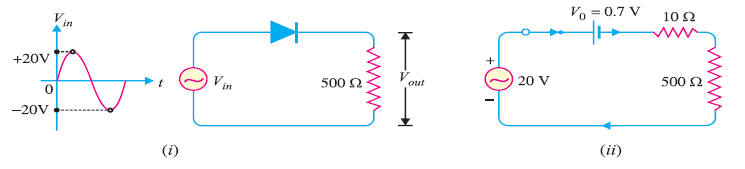
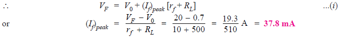
(i) The peak current through the diode will occur at the instant when the input voltage reaches positive peak i.e. Vin = VF = 20 V.

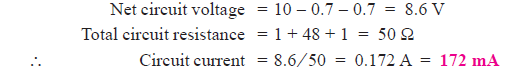
Q2. Find the current through the diode in the circuit shown in Fig. 2(i). Assume the diode to be ideal.
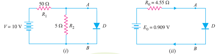
We shall use Thevenin’s theorem to find current in the diode. Referring to Fig. 2(i),
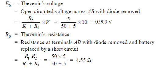
Fig. 2 (ii) shows Thevenin’s equivalent circuit. Since the diode is ideal, it has zero resistance
Q3. Calculate the current through 48 Ω resistor in the circuit shown in Fig. 3 (i). Assume the diodes to be of silicon and forward resistance of each diode is 1 Ω.
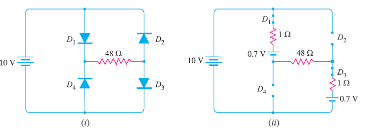
Diodes D1 and D3 are forward biased while diodes D2 and D4 are reverse biased. We can, therefore, consider the branches containing diodes D2 and D4 as “open”.
Replacing diodes D1 and D3 by their equivalent circuits and making the branches containing diodes D2 and D4 open, we get the circuit shown in Fig. 3 (ii). As we know for a silicon diode, the barrier voltage is 0.7 V.
Q4. Determine the current I in the circuit shown in Fig. 4 (i). Assume the diodes to be of silicon and forward resistance of diodes to be zero.
The conditions of the problem suggest that diode D1 is forward biased and diode D2 is reverse biased. We can, therefore, consider the branch containing diode D2 as open as shown in Fig. 4 (ii).
Further, diode D1 can be replaced by its simplified equivalent circuit.
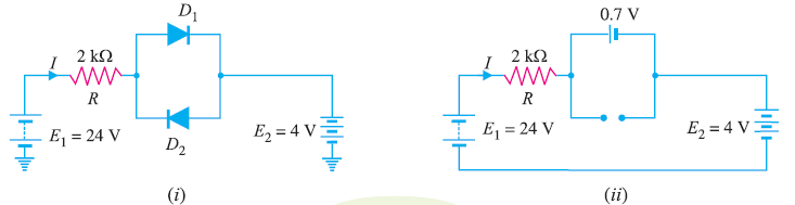
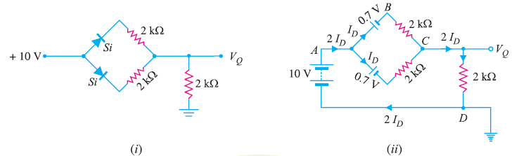
Q5. Find the voltage V A in the circuit shown in Fig. 5 (i). Use simplified model.
It appears that when the applied voltage is switched on, both the diodes will turn “on”. But that is not so. When voltage is applied, germanium diode (V0 = 0.3 V) will turn on first and a level of 0.3V is maintained across the parallel circuit.
The silicon diode never gets the opportunity to have 0.7 V across it and, therefore, remains in open-circuit state as shown in Fig.5(ii).
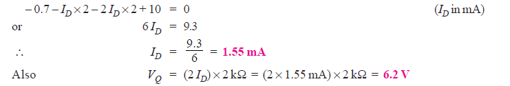
Q6. Find V Q and I D in the network shown in Fig. 6(i). Use simplified model.
Replace the diodes by their simplified models. The resulting circuit will be as shown in Fig. 6 (ii).
By symmetry, current in each branch is I D so that current in branch CD is 2I D .
Applying Kirchhoff’s voltage law to the closed circuit ABCDA, we have,
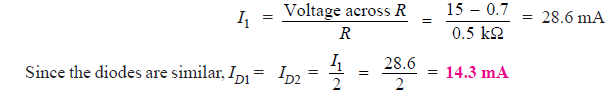
Q7. Determine current through each diode in the circuit shown in Fig. 7 (i). Use simplified model. Assume diodes to be similar.

The applied voltage forward biases each diode so that they conduct current in the same direction. Fig. 7 (ii) shows the equivalent circuit using simplified model. Referring to Fig. 7 (ii),
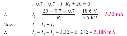
Q8. Determine the currents I1, I2 and I3 for the network shown in Fig. 8(i). Use simplified model for the diodes.

As we can see in Fig. 8 (i) both diodes D1 and D2 are forward biased. Using simplified model for the diodes, the circuit shown in Fig. 8(i) becomes the one shown in Fig. 8 (ii).
Applying Kirchhoff’s voltage law to loop ABCDA in Fig. 8 (ii), we have,
Q9. Determine if the diode (ideal) in Fig. 9 (i) is forward biased or reverse biased.
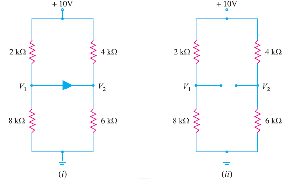
Let us assume that diode in Fig.9 (i) is OFF i.e. it is reverse biased.
The circuit then becomes as shown in Fig. 9(ii). Referring to Fig. 9 (ii), we have,
Now V1 – V2 = 2V is enough voltage to make the diode forward biased. Therefore, our initial assumption was wrong, and diode is forward biased.
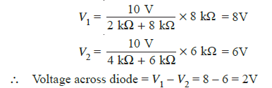
Q10. Determine the state of diode for the circuit shown in Fig. 10 (i) and find I D and V D . Assume simplified model for the diode.
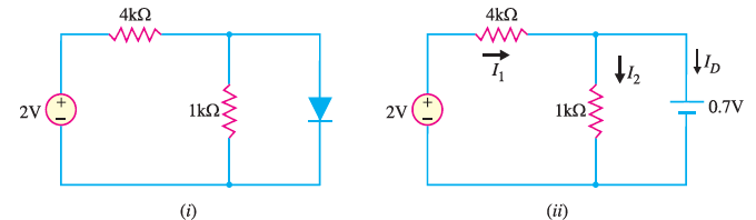
Let us assume that the diode is ON. Therefore, we can replace the diode with a 0.7V battery as shown in Fig. 10 (ii). Referring to Fig.10 (ii), we have,
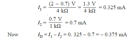
Since the diode current is negative, the diode must be OFF and the true value of diode current is ID =0 mA. Hence our initial assumption was wrong.
In order to analyse the circuit properly, we should replace the diode in Fig. 10 (i) with an open circuit as shown in Fig.10(iii).
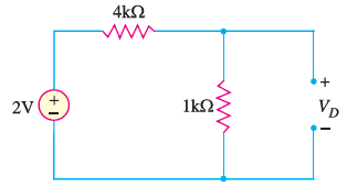
Fig.10 (iii)
The voltage VD across the diode is :
We know that 0.7V is required to turn ON the diode. Since VD is only 0.4V, the answer confirms that the diode is OFF.

Hi! I am Sasmita . At ElectronicsPost.com I pursue my love for teaching. I am an M.Tech in Electronics & Telecommunication Engineering. And, if you really want to know more about me, please visit my "About" Page. Read More
Diode Circuit Analysis
Published Mar 03, 2020
So we've learned about diodes in previous tutorials. But today we're going to be solving circuits with diodes and then we're going to be finding what the quiescent or Q-point is for those diodes and we're going to be talking about the benefits of each of these methods.
The Q-point is basically that point around which you don't expect a whole lot of variation in the current or the voltage. And with diodes, there's a couple of different ways to approach it. And we're going to go over them really quick, we're going to talk about two of them, talk about why we're not going to be doing them. And then we're going to do two examples with two of the other methods. So again, we're looking for the voltage across it and the current through it.
Load Line Analysis
So the first thing that you can do, and one of the ones that we don't recommend is called the load line analysis. And that's where you take the diode that you're going to be using in the circuit and you physically take it into a lab, put a voltage across it and measure the current through it. And as you increase the voltage, you create your graph to show exactly what the current is when you're at a certain voltage across that diode and then you use that in your actual circuit and you solve for things and you move things around. And it's 1) huge pain to get the data in the first place and 2) it's still a huge pain to use later. You know, depending on what you're doing, it may be necessary, probably not.
Mathematical Model
The second thing you can do is actually a mathematical model. With this math model, you can see that you have the voltage drop across the diode on the left hand of the equation, and then you have a bunch of other stuff. So you have the V S which is the source voltage across the diode, R is the resistance of the resistor that is in series with the diode. And then you have your I S , which is the current through the diode and resistor. But you also notice on the right hand of the equation, there's another V D , another voltage drops.
So this is an iterative thing, where you have to go through and not only do you have to have all of those other things figured out, you then have to iterate and try and find exactly what that voltage drop is going to be over that.
So it's a pain and again, you probably don't need it. It doesn't make a whole lot of sense, but it is one method of figuring out what that voltage drop across the diode will be if you have all of the other information anyway. So kind of dumb, but I just wanted to introduce those because there are multiple ways of approaching this. And just because there's a lot of ways doesn't mean that you should use all of them. Again, if you're going to be doing your PhD thesis, then do what you got to do.
Ideal Diode Model
But the third way that we're going to talk about this is the simplest way and in another tutorial we talked about this. And this is where we just assume that if a diode is forward biased, there is no voltage drop across it. And if it's reverse bias, then the voltage is whatever, it just happens to be in the circuit. So as we do this, there's going to be four steps that we follow one when solving a circuit with the ideal diode model.
So here, I'm going to create a circuit. I got this from taking a microelectronics class at Boise State, just pulling off there and if I were wise, I would have practiced this beforehand and we will see if it goes to complete heck in a hand basket again. And I am creating this circuit, so that we can try to go through those four steps that I just mentioned.
So the first thing just created the circuit. Now I have to look at the circuit. And wow, that is a terrible resistor that, that may be one of the worst resistors I've ever made in my entire life. So we're looking at the circuit, and we're deciding which diode is going to be forward biased and which diode is going to be reverse biased. And so I have to just kind of guess, looking at it and think, okay, I've got nine volts here. And so if these were both forward biased, I would have zero volts here, which would mean that I'd have current flowing this way that makes sense, and then I'd have a negative six volts there. But then is that being a much smaller resistor than that? Is that going to make it so I'm actually getting flow this way? Or is the flow going to be going back that way? And you just have to look at it and make that assumption and that is the very first step.
So on this one, I'm going to look at this and say, I believe that this is going to be forward so it's going to be treated as a short circuit in this ideal diode model, and then this will also be treated as a short circuit in the ideal model. So let's recreate this with those assumptions.
So we're going to go down, and that actually didn't get any better. And then we'll put a note there, show that as a short circuit to ground. And then we'll go there and show that as a short circuit to 43k and -6 volts, +9 volts, 22k, and 43k. So that's our second step is now that we've made our assumptions we've recreated the circuit.
The third step is now doing some basic circuit analysis to see if our assumptions actually work.
So in this case, we are going to have basically, two... let me do my ohm's law in the corner like I always do, just keep things straight in my head, we're going to have our two currents right here. I call this I 1 , and I 2 . And I 1 is simply nine volts minus zero volts over 22k and then I 2 is going to be zero volts minus -6 volts over 43k. And so let me throw that into a calculator really quick because there's no way I'm gonna be able to do that in my head. And that comes out to be about 409 microamps. And this comes out to be about 140 microamps. Okay, so that looks good.
Now one of the interesting things here is that I 1 is not the current that goes through this diode. It's the current that goes through the diode and also through this diode. So we're going to mark that as I 3 and we are simply going to find I 3 as I 3 equals I 1 minus I 2 . So that is going to be 409 microamps minus 140 microamps and that will give us a number that, again, I can't do in my head, 269 microamps, okay.
So now we have actually solved and we have an assumption that we are going to have zero volts across both of these diodes and we have assumed that we are going to have 140 microamps through that and 269 microamps through that way. So our quiescent point or Q-point for, let's do some retcon, for D 1 is our voltage is going to be zero volts and our current is going to be 269 microamps and D 2 … Wow, I've just I'm having one of those days, D 2 , subs of two is also going to be zero volts and 140 microamps.
Now, frankly, the the way I did this, I often see it done another way where you actually have the current first I'm used to just doing volts and amps. But you might see it where people say, hey actually do current first so 140 microamps and then zero volts in the that will be your Q-point for D 1 and your Q-point for D 2 .
Now this is where we get to our final step in the process. And this is where we look at it and say, Does this make sense? Now for there to be zero volts across these diodes, we need to have a positive current in these directions that we've established. So as we look at this and we say all right, D 1 has a positive 269 microamps in that direction and D 2 has a positive 140 microamps in that direction. And we are assuming that those are both zero volts. All of these numbers make sense with the way we've set up. So we can actually look at this and say, Yes, my assumption that both of these are forward biased is correct.
And so this is how you do it with an ideal model, when you're trying to solve for the diode, and it's pretty straightforward in terms of making it simple, just shorting that stuff. And the only difference between this in the fourth and final method that we're going to go over is that in the constant voltage drop model, we have to make things more interesting in there. You can't just put shorts or opens, well, I guess you can still put opens, but let's get into that right now.
Constant Voltage Drop Model
So let's do another circuit. So this time, we're going to start with +6 volts. So have our node right there, have our 43k right there, another node. And if we want to zoom through this, that's totally fine with me. You know, I've had people tell me that I should have been a lot of things, but an artist was never one of them. I don't even know. Was I trying to put -9? -9 volts. Okay, is that legible? I think that's legible. Okay, then we have our 22k. So now we are set up for our constant voltage drop (CVD) style.
So same exact four steps that we did in the previous one of first looking at it, making some assumptions. Second, drawing out the model with our assumptions. Third, solving for that model. And then fourth, going back, seeing if our assumptions work. And if they do great, we move forward. If not, we go back and change our assumptions and do the entire thing over again.
But the difference is with this should have pointed this out. This is very, very crucial difference between this model and the ideal model is in this one, we're going to assume that it's a 0.7 volt drop. So if we are forward biased, it's not going to just be alright, forward bias. Let's put in a short we're actually going to make model it with a voltage drop, a voltage source, of 0.7 volts. So six volts, I'm still going to make an approximation that this is going to be about zero volts. If that is forward, in reality, it'd be 0.7. And that would put 0.7, -9, I think that this is going to be forward biased and this is going to be reverse biased.
So now on step two - create that model, six volts down... why is that so bad. And then I put in my voltage source of 0.7 volts and then I put this as an open to -9 volts and 22k, step two is done.
Step three, let's actually solve for this. Now with that being gone that makes this pretty simple. So let's see if I can, in this case, I 1 will be the same thing as going through that and then we have I 2 which is going to be pretty straightforward because that's going to be zero because it's open but we model it we have I 1 . Let's see what should I do this, I 1 equals six minus 0.7 over 43k divided by 43,000. It's gonna give me 123 microamps and it is going to put this voltage right here it's going to be 0.7, and this voltage at this node is going to be -9 volts and we assume I 2 is just going to be zero because nothing can flow through that.
Okay, so now let's take this and establish our Q-points. So we are going to again retcon this because I don't do things in order like I should, D 1 one equals… Let's put this as a current first 123 microamps and 0.7 volts. And then D 2 's Q-point is going to be zero amps and -8.3… Nope, nope, I totally got that backwards because I cannot do math in my head. So that is 0.7 minus and I went the wrong direction. So this should be -9.7. Now the beautiful thing is that it doesn't change the way that it's biased. It just changes the fact that I was totally screwed up.
So now again, did everything taking our time breathing, making sure we're not making mistakes. Come on, Josh. Don't make mistakes. Now we verify that this is actually set up. So we assumed that D 1 was going to be forward biased. And we assumed D 2 was going to be reverse biased. So as we look at this, we have a positive current through it, and then that 0.7 across it just because that's what we have. And then D 2 , we have zero current through in a big -9.7 volts across it.
So both of these are correct in that we assumed this was going to be forward biased, and it is, and we assume this is going to be reversed biased, and it also is. Now again, either of these have been wrong, we'd have to go back, you'd have to say, all right, I was wrong here. Let's assume that is forward biased. And we'd have to recreate this, redo all that, which would of course, increase the chance of me being unable to do simple arithmetic again. But hopefully, that is more straightforward.
So again, the only difference between the constant voltage drop and the ideal model is the fact that you put in a voltage source to say, okay, we're losing 0.7, or whatever your assumption is, 0.7 volts across this diode. And in most cases, it won't make a difference, but on occasion it will, it definitely will make things more complicated for you.
So four different types of ways of solving four diodes in an equation, four steps in the way we do the ideal and the constant voltage drop. And despite this, despite the iteration, and despite the fact that I can't do math, this isn't that bad. Doing the constant voltage drop and doing the ideal model are pretty straightforward. So, just take your time, go through them. Make sure that at the end, you look at it and say, does it actually make sense? So hopefully that helped. If it didn't confuse you, that is fantastic. Hope you liked this, subscribe to our channel . We love people to subscribe and ask questions and learn more about electronics. We'll catch you on the next one.
Authored By
Josh bishop.
Interested in embedded systems, hiking, cooking, and reading, Josh got his bachelor's degree in Electrical Engineering from Boise State University. After a few years as a CEC Officer (Seabee) in the US Navy, Josh separated and eventually started working on CircuitBread with a bunch of awesome people. Josh currently lives in southern Idaho with his wife and four kids.
Related Tutorials
- Electronic Basics
Explore CircuitBread
- 223 Tutorials
- 9 Textbooks
- 12 Study Guides
- 102 EE FAQs
- 295 Equations Library
- 205 Reference Materials
- 91 Glossary of Terms
Friends of CircuitBread
Browse Parts by Product
Request A Product Sample
Product Samples Upon Request
Get the latest tools and tutorials, fresh from the toaster.
What are you looking for?
Message sent.
Thanks for the message, our team will review it shortly.
Log In or Sign Up
Username should have no spaces, underscores and only use lowercase letters.
Thanks for joining CircuitBread!
Please confirm your email address by clicking the link in the email we sent you.
Didn't receive anything? Resend now.

- school Campus Bookshelves
- menu_book Bookshelves
- perm_media Learning Objects
- login Login
- how_to_reg Request Instructor Account
- hub Instructor Commons
- Download Page (PDF)
- Download Full Book (PDF)
- Periodic Table
- Physics Constants
- Scientific Calculator
- Reference & Cite
- Tools expand_more
- Readability
selected template will load here
This action is not available.
2.4: Diode Circuit Models
- Last updated
- Save as PDF
- Page ID 25385

- James M. Fiore
- Mohawk Valley Community College
One thing is very clear from the characteristic curve of the diode: It is not a linear bilateral 1 device, quite unlike a resistor. Consequently, we cannot use the superposition technique to solve diode circuits unless we have a priori knowledge about it, that is, whether or not it is forward- or reverse-biased. For example, we can imagine a circuit comprised of two voltage sources, resistors and a diode. By itself, one of the voltage sources might forward-bias the diode while the other would reverse-bias it. Obviously, a diode cannot be both forward and reverse-biased at the same time.
A second problem we face with circuit analysis is the added complexity of the Shockley equation. For speed and ease of computation we find it useful to model the diode with simpler circuit elements. Three diode models are shown in Figure \(\PageIndex{1}\).

Figure \(\PageIndex{1}\): Simplified diode models. Top to bottom: first, second and third approximations, increasing in accuracy.
The first approximation is the simplest of the three. It treats the diode as a simple dependent switch: the switch is closed if the diode is forward-biased and open if it is reverse-biased. The second approximation adds the effect of the forward voltage. \(V_{knee}\) is the “turn-on” potential required to overcome the energy hill. It would be 0.7 volts for a silicon device. The third approximation is the most accurate of the three. A close look at the characteristic curve of Figure 2.2.4 shows that once the knee voltage is reached, the curve does not transition to a perfect vertical line. Instead, there remains some positive, non-infinite slope. That is, the voltage continues to increase, although modestly, with further increases in current. We can approximate this effect as a small resistive value, \(R_{bulk}\). The three corresponding I-V plots are shown in Figure \(\PageIndex{2}\). Compare these to Figure 2.2.6 and note the increasing accuracy.

Figure \(\PageIndex{2}\): I-V curves for simplified diode models. Top to bottom: first, second and third approximations.
In many applications the second approximation will yield sufficiently accurate results and we will tend to make greatest use of it. Just remember that these are behavioral models; don't think that there are literally 0.7 volt sources or little resistors in the diodes.
It should be noted that \(R_{bulk}\) does not represent the “diode resistance” per se, rather, it models a minimum value. There really is no such thing as a singular diode resistance. We can, however, talk about the effective resistance of a diode in a particular circuit in both DC and AC terms.
The key to understanding this concept is to remember that resistance is a linear function, a straight line on a I-V graph. Therefore, we need to find a straight line “fit” for the diode curve. Two possibilities are shown in Figure \(\PageIndex{3}\).

Figure \(\PageIndex{3}\): Diode effective resistance for DC and AC.
The red curve is the diode's characteristic curve (arbitrary current values are shown). For some particular DC circuit, a specific current will flow through the diode which will produce a particular voltage, denoted on the graph as the operating point. If we simply compute the ratio of that voltage to the driving current, we wind up with a resistance. This is the effective DC resistance of the diode under these circuit conditions and is represented by the blue line. That is, the reciprocal of the slope of the blue line is the effective DC resistance. Obviously, if we shift the operating point along the red diode curve, the slope of the intersecting blue line changes and therefore we arrive at a new DC resistance. The higher the current, the lower the effective DC resistance.
Instead of just DC, the diode might see a combination of DC and AC signals. Visualize this as adding a small AC variation on top of the DC. We can imagine the operating point moving along the red diode curve, back and forth about the operating point. If we divide the small AC voltage variation by its associated AC current variation, we wind up with the AC equivalent resistance, also known as the dynamic resistance. Graphically, we can think of this as finding the slope of a line that is tangent to the operating point (the purple line). This will in fact, be an average value across the AC variation. It should also be apparent that the effective AC resistance must be smaller than its DC counterpart because the AC approximation (purple line) must be steeper than the DC approximation (blue line) 2 . It is time for a few illustrative examples.
Example \(\PageIndex{1}\)
Consider the resistor-diode circuit of Figure \(\PageIndex{4}\). Assume the voltage source is 12 volts and the resistor is 2 k\(\Omega\). Further, assume the diode is silicon and its bulk resistance is 10 \(\Omega\). Using the three diode approximations, compute the circulating current.

Figure \(\PageIndex{4}\): Schematic for Example \(\PageIndex{1}\).
First, note that the diode is forward-biased. This must be the case because there is a single voltage that is larger than the knee voltage and its positive terminal is attached to the diode's anode. No matter which approximation we use, Kirchhoff's voltage law (KVL) must be true so it will be a matter of summing the available voltage drops versus resistance(s).
Using the first approximation:
Here we assume the diode is a closed switch. Consequently all of the source voltage must drop across the single resistor.
\[I = \frac{E}{R} \nonumber \]
\[I = \frac{12V}{2 k\Omega} \nonumber \]
\[I = 6mA \nonumber \]
Using the second approximation:
In this instance we include the knee voltage.
\[I = \frac{E−V_{knee}}{R} \nonumber \]
\[I = \frac{ 12 V−0.7 V}{2 k\Omega} \nonumber \]
\[I = 5.65mA \nonumber \]
Using the third approximation:
The most accurate of the three, we include both the knee voltage and bulk resistance.
\[I = \frac{ E−V_{knee}}{R+R_{bulk}} \nonumber \]
\[I = \frac{ 12 V−0.7 V}{2 k\Omega+10 \Omega} \nonumber \]
\[I = 5.622mA \nonumber \]
In this particular case the difference between the second and third approximations is less than 1%. It is also worth noting that the third approximation predicts a diode voltage of slightly more than 0.7 volts (approximately 0.756 volts) due to the additional potential across the bulk resistance.
Example \(\PageIndex{2}\)
Determine the circulating current for the circuit in Figure \(\PageIndex{5}\). Also find the diode and resistor voltages. Assume the power supply is 20 volts, the diode is silicon and the resistor is 2 k\(\Omega\).

Figure \(\PageIndex{5}\): Schematic for Example \(\PageIndex{2}\).
This problem is deceptively easy. Note that the positive terminal of the source is connected to the cathode. As there are no other sources in the circuit, the diode must be reverse-biased. The model for a reverse-biased diode is an open switch and the circulating current in an open circuit is zero. Therefore, the resistor voltage must also be zero and values for the knee voltage and bulk resistance are not needed. In order to satisfy KVL, the diode voltage will equal the source of 20 volts (+ to − from cathode to anode).
The only time this would not be the case is if the reverse breakdown voltage of the diode is less than the 20 volt source. In that case the diode voltage would equal the breakdown voltage with the remainder of the source voltage dropping across the resistor.
Example \(\PageIndex{3}\)
Determine the circulating current for the circuit in Figure \(\PageIndex{6}\). Also find the diode and resistor voltages. Assume the power supply is 9 volts, the diodes are silicon and \(R_1\) = 1 k\(\Omega\), \(R_2\) = 2 k\(\Omega\).

Figure \(\PageIndex{6}\): Schematic for Example \(\PageIndex{3}\).
According to KVL, the applied source must equal the sum of the voltage drops across the resistors and diodes as this is a single loop. Both diodes are forward-biased (conventional current entering the anodes).
\[I = \frac{ E−V_{knee1} − V_{knee2}}{R_1+R_2} \nonumber \]
\[I = \frac{ 9V−0.7V−0.7V}{1k \Omega +2 k\Omega} \nonumber \]
\[I = 2.533mA \nonumber \]
Note that if either diode was reversed, there would be no current flow and all of the source potential would drop across the reversed diode.
Example \(\PageIndex{4}\)
Determine the source current and resistor voltages for the circuit in Figure \(\PageIndex{7}\). Also find the resistor voltages if the diode polarity is reversed. Assume the power supply is 10 volts, the diode is silicon and the resistors are 1 k\(\Omega\) each.

Figure \(\PageIndex{7}\): Schematic for Example \(\PageIndex{4}\).
As \(D\) and \(R_2\) are in parallel they must have the same voltage drop. Also, the diode is forward-biased. Therefore, the voltage across \(R_2\) must be approximately 0.7 volts, leaving 9.3 volts to drop across \(R_1\). The current through \(R_1\) is the source current.
\[I = \frac{E−V_D}{R_1} \nonumber \]
\[I = \frac{10 V−0.7 V}{1k \Omega} \nonumber \]
\[I = 9.3mA \nonumber \]
If the diode is reversed it behaves as an open switch. The circuit reduces to a simple 1:1 voltage divider, each resistor dropping half of the supply, or 5 volts each.
Computer Simulation
To verify our results, Example \(\PageIndex{4}\) is simulated. The circuit is captured as shown in Figure \(\PageIndex{8a}\). This particular example is shown in Multisim although any decent quality simulator will do. The very common 1N4148 switching diode is used here. Another popular choice would be the 1N914 switching diode or a 1N400X series rectifier.

Figure \(\PageIndex{8a}\): The circuit of Example \(\PageIndex{4}\) in Multisim.
Next, a DC Operating Point analysis is performed. The results are shown in Figure \(\PageIndex{8b}\). Note that the diode potential is just under the 0.7 volt approximation. From this we can deduce that the voltage drop across the first resistor must be slightly more than 9.3 volts, producing a current slightly more than 9.3 mA.

Figure \(\PageIndex{8b}\): DC Operating Point simulation results for the circuit of Example \(\PageIndex{4}\).
Finally, Figure \(\PageIndex{8c}\) shows the results when the diode is reversed in the circuit. The second resistor (node 3 to ground) shows 5 volts as expected. Therefore, the first resistor must also be dropping 5 volts.

Figure \(\PageIndex{8c}\): Simulation of Example \(\PageIndex{4}\) using reversed diode orientation.
Before moving on to another topic, let's take a look at a somewhat more involved example using multiple diodes.
Example \(\PageIndex{5}\)
Determine the diode and resistor voltages for the circuit in Figure \(\PageIndex{9}\). Assume the diodes are silicon.

Figure \(\PageIndex{9}\): Schematic for Example \(\PageIndex{5}\).
The first thing to notice is that \(D_1\) is forward-biased while \(D_2\) is reverse-biased. Therefore, the 20 volt source must equal the drop across \(D_1\) and the two resistors. \(D_2\) will take on whatever the drop across the 2 k\(\Omega\) works out to as they are in parallel.
\[I = \frac{E−V_{D1}}{R_1+R_2} \nonumber \]
\[I = \frac{20 V−0.7V}{1k\Omega +2 k\Omega} \nonumber \]
\[I = 6.433mA \nonumber \]
Note that virtually no current flows down through \(D_2\) as it is reverse-biased. Using Ohm's law, the drop across the first resistor is 6.433 volts and for the second resistor, 12.867 volts.
1 The I-V plot is not a straight line (linear) and the forward and reverse quadrants are not identical (bilateral).
2 The dynamic resistance of a PN junction may be approximated as 26 mV/\(I_{junction}\). This will be shown in an upcoming chapter.
March 30, 2024
Find The Best Diode & Component Deals Quick!

How to Solve the Diode Circuits (Explained with Examples)
In this video clip, various approaches for resolving the diode circuits have actually been reviewed.
Both techniques have actually been gone over in the video clip and also making use of the diode estimation technique, various circuit troubles have actually been resolved.
There are 2 techniques for resolving/ evaluating the diode circuits. 1) Graphical Method 2) Diode Approximation
The timestamps for the various subjects covered in the video clip:
1:02 Graphical Method (Using the Load Line).
3:19 Diode Approximations.
4:29 How to Solve a circuit trouble utilizing diode estimation.
7:46 Example 1 (Series link of Diode).
9:54 Example 2.
12:11 Example 3 (Parallel Connection of Diode).
13:41 Example 4 (Parallel Connection of Diode with various diodes (Si and also Ge)).
16:11 Example 5 (Parallel link of diode with various voltages).
The web link for the various other helpful video clips associated with diode:. 1) Introduction to a diode as well as V-I qualities of the diode. https://www.youtube.com/watch?v=EdUAecpYVWQ.
Graphical Method:. In visual technique, the tons line is made use of the V-I contour of the diode. The lots line offers the feasible worths of voltage and also current of the diode for the provided circuit. The crossway of the V-I contour of the tons as well as the diode line provides the operating voltage as well as current of the diode.
Diode Approximation:. In the diode estimate, the diode is changed by the comparable circuit. The worths of voltage and also current of the diode by this approach is not precise, utilizing the diode estimation the circuits can be addressed/ evaluated extremely conveniently.
2) The diode resistance Explained:. https://www.youtube.com/watch?v=hag5ss1ZxH0.
Follow me on Instagram:. https://www.instagram.com/all_about.electronics/.
#HowToSolveDiodeCircuits. #DiodeExamples.
This video clip will certainly be valuable to all trainees of scientific research and also design in finding out just how to resolve the diode circuit issues.
Follow me on YouTube:. https://www.youtube.com/allaboutelectronics.
Follow me on Facebook:. https://www.facebook.com/ALLABOUTELECRONICS/.
Songs Credit:. http://www.bensound.com/.
More Great Deals...


What is Diode Approximation : Types and Diode Models
Diodes are mainly unidirectional devices. It offers low resistance when a forward or positive voltage is applied and has high resistance when the diode is reverse biased. An ideal diode has zero forward resistance and zero voltage drop. The diode offers high reverse resistance, resulting in zero reverse currents. Though ideal diodes do not exist, near-ideal diodes are used in some applications. The supply voltages are generally much larger than the forward voltage of a diode and thus V F is assumed to be constant. Mathematical models are used to approximate characteristics of silicon and germanium diode when the load resistance is typically high or very low. These methods help to solve real-world problems. This article discusses what is diode approximation, types of approximations, problems and approximate diode models.
What is a Diode?
A diode is a simple semiconductor with two terminals called as anode and cathode. It allows the flow of current in one direction (forward direction) and restricts the current flow in the opposite direction (the reverse direction). It has low or zero resistance when forward biased and high or infinite resistance when reverse biased. The terminals anode refers to positive lead and cathode refers to the negative lead. Most of the diodes conduct or allow current to flow when the anode is connected with a positive voltage. Diodes are used as rectifiers in power supply.

What is Diode Approximation?
Diode approximation is a mathematical method used to approximate the nonlinear behavior of real diodes to enable calculations and circuit analysis. There are three different approximations used to analyze the diode circuits.
First Diode Approximation
In the first approximation method, the diode is considered as a forward-biased diode and as a closed switch with zero voltage drop. It is not apt to use in real-life circumstances but used only for general approximations where preciseness is not required.

Second Diode Approximation
In the second approximation, the diode is considered as a forward-biased diode in series with a battery to turn on the device. For a silicon diode to turn on, it needs 0.7V. A voltage of 0.7V or greater is fed to turn on the forward-biased diode. The diode turns off if the voltage is less than 0.7V.

Third Diode Approximation
The third approximation of a diode includes voltage across the diode and voltage across bulk resistance, R B . The bulk resistance is low, such as less than 1 ohm and always less than 10 ohms. The bulk resistance, R B corresponds to the resistance of p and n materials. This resistance changes based on the amount of forwarding voltage and the current flowing through the diode at any given time.
The voltage drop across the diode is calculated using the formula
V d = 0.7V + I d *R B
And if R B < 1/100 R Th or R B < 0.001 R Th , we neglect that

Diode Approximation Problems with Solutions
Let’s now look at two 2 examples of diode approximation problems with solutions
1). Look at the circuit below and use the second approximation of diode and find the current flowing through the diode.

I D =(V s – V D )/R = (4-0.7)/8 = 0.41A
2). Look at both of the circuits and calculate using the third approximation method of diode

For fig (a)
Adding 1kΩ resistor with bulk resistor 0.2Ω doesn’t make any difference in current flowing
I D = 9.3/1000.2= 0.0093 A
If we don’t count 0.2Ω, then
I D = 9.3/1000=0.0093 A
For fig (b)
For load resistance of 5Ω, ignoring bulk resistance of 0.2Ω brings a difference in current flow.
Therefore, bulk resistance has to be considered and the correct value of current is 1.7885 A.
I D =9.3/5.2=1.75885 A
I D =9.3/5=1.86 A
Summarizing, if the load resistance is small, the bulk resistance is taken into effect. However, if the load resistance is very high (ranging to several kilo-ohms), then bulk resistance has no effect on the current.
Approximate Diode Models
The diode models are mathematical models used for the approximation of diode’s actual behavior. We shall discuss the modeling of p-n junction connected in a forward-biased direction using various techniques.
Shockley Diode Model
In the Shockley diode model equation, the diode current I of a p-n junction diode is related to the diode voltage VD. Assuming that VS>0.5V and ID is much higher than IS, we represent the VI characteristic of a diode by
i D = i S (e VD /ηVT – 1) —— (i)
With Kirchhoff’s loop equation, we obtain the following equation
i D = (V S – V D /R) ———- (ii)
Assuming that the diode parameters are and η are known, while ID and IS are unknown quantities. These can be found using two techniques – Graphical analysis and Iterative analysis
Iterative Analysis
An iterative analysis method is used to find diode voltage VD with respect to VS for any given series of values using a computer or calculator. The equation (i) can be reorganized by dividing it by IS and adding 1.
e VD/ηVT = I/I S +1
By applying the natural log on both sides of an equation, the exponential can be removed. The equation reduces to
V D /ηV T = ln(I/I S +1)
Substituting for (i) from (ii) as it satisfies Kirchhoff’s law and the equation reduces to
V D /ηV T = (ln(V S –V D )/RI S ) +1
V D = ηV T ln((V S – V D )/RI S +1)
As Vs is known to value, VD can be guessed and the value is put in the right-hand side of the equation and performing continuous operations, a new value for VD can be found. Once VD is found, Kirchhoff’s law is used to find I.
Graphical Solution
By plotting the equations (i) and (ii) on the I-V curve, an approximate graphical solution is obtained at the intersection of two graphs. This intersecting point on the graph satisfies equations (i) and (ii). The straight line on the graph represents the load line and the curve on the graph represents the diode characteristic equation.

Piecewise Linear Model
As the graphical solution method is highly complicated for composite circuits, an alternative approach of diode modeling is used, known as piecewise linear modeling. In this method, a function is broken down into multiple linear segments and used as a diode approximation characteristic curve.
The graph shows the VI curve of a real diode that is approximated using a two-segment piecewise linear model. A real diode is classified into three elements in series: an ideal diode, the voltage source, and a resistor . The tangent drawn at the Q-point to the diode curve and the slope of this line is equal to the reciprocal of the diode’s resistance at the Q-point.

Mathematically Idealized Diode
A mathematically idealized diode refers to an ideal diode. In this type of an ideal diode, the current flowing is equal to zero when the diode is reverse biased. The characteristic of an ideal diode is to conduct at 0V when a positive voltage is applied and the current flow would be infinite and diode behaves like a short circuit. The characteristic curve of an ideal diode is shown.

1). Which diode model represents the most accurate approximation?
The third approximation is the most accurate approximation as it includes a diode voltage of 0.7V, voltage across internal bulk resistance of a diode, and reverse resistance offered by a diode.
2). What is the breakdown voltage of the diode?
The breakdown voltage of a diode is the minimum reverse voltage applied to make the diode breakdown and conduct in the reverse direction.
3). How do you test a diode?
To test a diode, use a digital multimeter
- Change the multimeter selector switch to diode check mode
- Connect the anode to the positive lead of multimeter and cathode to the negative lead
- Multimeter shows a voltage reading between 0.6V to 0.7V and knows that the diode is working
- Now reverse the connections of multimeter
- If the multimeter displays an infinite resistance (over range) and knows that the diode is working
4). Is diode a current?
A diode is neither a current-controlled nor a voltage-controlled device. It conducts if positive and negative voltages are given correctly.
This article discussed the three types of diode approximation method. We discussed how a diode can be approximated when the diode acts as a switch with few numerical. Finally, we discussed various types of approximate diode models. Here is a question for you, what is the function of a diode?
Share This Post:

- Electronics
- Communication
- Free Circuits
- Interview Questions
- ECE Projects
- EEE Projects
- Project Ideas
- Resistor Color Code Calculator
- Ohms Law Calculator
- Circuit Design
- Infographics
with Answers, Solution | Semiconductor Electronics | Physics - Example Solved Numerical Problems | 12th Physics : UNIT 10a : Semiconductor Electronics
Chapter: 12th physics : unit 10a : semiconductor electronics, example solved numerical problems, junction diode - numerical problems questions with answers, solution, example 9. 1.
An ideal diode and a 5 Ω resistor are connected in series with a 15 V power supply as shown in figure below. Calculate the current that flows through the diode.

The diode is forward biased and it is an ideal one. Hence, it acts like a closed switch with no barrier voltage. Therefore, current that flows through the diode can be calculated using Ohm’s law.
V = IR
I = V/R = 15/5 = 3 A
EXAMPLE 9. 2
Consider an ideal junction diode. Find the value of current flowing through AB is

The barrier potential of the diode is neglected as it is an ideal diode.
The value of current flowing through AB can be obtained by using Ohm’s law
I = V/R = 3 - (-7) / 1× 10 3 /10 3 = 10 =10 -2 A = 10 mA
Zener diode - Numerical Problems Questions with Answers, Solution
Example: 9.3.
Find the current through the Zener diode when the load resistance is 1 KΩ. Use diode approximation.

Voltage across AB is V Z = 9V
Voltage drop across R = 15 - 9 = 6V
Therefore current through the resistor R,
I = 6 / 1×10 3 =6 mA
Voltage across the load resistor = V AB = 9 V
Current through load resistor
I L = V AB /R L = 9 / 2×10 3 = 4.5 mA
The current through the Zener diode,
I Z = I − I L =6 mA − 4.5 mA =1.5 mA
Optoelectronic devices using Diodes - Numerical Problems Questions with Answers, Solution
EXAMPLE 9.4
Determine the wavelength of light emitted from LED which is made up of GaAsP semiconductor whose forbidden energy gap is 1.875 eV. Mention the colour of the light emitted (Take h = 6.6 × 10 -34 Js).
E g = h c / λ
λ= h c / E g = 6.6×10 −34 ×3 × 10 8 / 1.875×1.6×10 −19
= 660 nm
The wavelength 660 nm corresponds to red colour light.
Transistor action in the common base mode - Numerical Problems Questions with Answers, Solution
Example 9. 5.
In a transistor connected in the common base configuration, α=0.95 , I E =1 mA . Calculate the values of I C and I B .
α= I C / I E
I C =α I E =0.95×1=0.95 mA
I E = I B + I C
∴ I B = I C − I E =1−0.95=0.05 mA
Transistor in Common Emitter Mode - Numerical Problems Questions with Answers, Solution
EXAMPLE 9. 6
The output characteristics of a transistor connected in common emitter mode is shown in the figure. Determine the value of I C when V CE = 15 V. Also determine the value of I C when V CE is changed to 10 V.

When V CE = 15 V , I C = 1.5 μ A
When V CE is changed to 10 V , I C = 1.4 μ A
The collector current is independent of the collector- emitter voltage in the active region.
EXAMPLE 9.7
In the circuit shown in the figure, the input voltage V i is 20 V , V BE = 0 V and V CE = 0 V . What are the values of I B , I C , β ?

Bipolar Junction Transistor [BJT] - Numerical Problems Questions with Answers, Solution
EXAMPLE: 9.8
The current gain of a common emitter transistor circuit shown in figure is 120. Draw the dc load line and mark the Q point on it. ( V BE to be ignored).

β = 120

Transistor as an oscillator - Numerical Problems Questions with Answers, Solution
Example 9. 9.
Calculate the range of the variable capacitor that is to be used in a tuned-collector oscillator which has a fixed inductance of 150 μH. The frequency band is from 500 kHz to 1500 kHz.

Logic gates - Numerical Problems Questions with Answers, Solution
EXAMPLE 9. 10
What is the output Y in the following circuit, when all the three inputs A, B, and C are first 0 and then 1?

EXAMPLE 9. 11
In the combination of the following gates, write the Boolean equation for output Y in terms of inputs A and B.

De Morgan’s Theorem - Numerical Problems Questions with Answers, Solution
EXAMPLE: 9 . 12
Simplify the Boolean identity
AC + ABC = AC
Step 1: AC (1 + B) = AC.1 [OR law-2]
Step 2: AC . 1 = AC [AND law – 2]
Therefore, AC + ABC = AC
Circuit Description

Thus the given statement is proved.
Space Wave Propagation - Numerical Problems Questions with Answers, Solution
Example 10.1.
A transmitting antenna has a height of 40 m and the height of the receiving antenna is 30 m. What is the maximum distance between them for line-of-sight communication? The radius of the earth is 6.4×10 6 m.

The total distance d between the transmitting and receiving antennas will be the sum of the individual distances of coverage.
d = d 1 + d 2
= √(2 R h ) + √(2 Rh 2 )
= √2√ R (√ h 1 + √ h 2 )
= √[2 × 6.4 ×10 6 ] × ( √40 + √30 )
=16 ×10 2 √5 ×(6.32 + 5.48)
=42217 m = 42.217 km
Numerical Problems
1. The given circuit has two ideal diodes connected as shown in figure below. Calculate the current flowing through the resistance R 1 [Ans: 2.5 A]

Barrier potential for ideal diode is zero. The diode D 1 is reverse biased, so it will block the current and diode D 2 is forward biased, so it will pass the current.
The given circuit becomes

Effective resistance R eff = R 1 + R 3 = 4Ω
Current through R 1 = V/R eff = 10/4 = 2.5A
2. Four silicon diodes and a 10 Ω resistor are connected as shown in figure below. Each diode has a resistance of 1Ω. Find the current flows through the 18Ω resistor. [Ans: 0.13 A]

In the given circuit D 2 & D 3 are in forward bias so they conduct current while D 1 &D 4 are in reverse bias so they do not conduct current. So the equivalents circuit will be

the effective resistance is R eff
= 1Ω + 10Ω + 1Ω = 12Ω
Here silicon diodes are used
∴ Barrier potential for Si is 0.7 V
Net potential (V net ) = 3 – 0.7 - 0.7
V net = 1.6 V
Current (I) = V net / R eff = 1.6 / 12 = 0.133A
3. Assuming V CEsat = 0.2 V and β = 50, find the minimum base current (I B ) required to drive the transistor given in the figure to saturation. [Ans: 56 µA]

V CE = 0.2V
R c = 1 k Ω
I B = ?

Ic = [ V CC – V CE ] / R C
= (3-0.2) / 10 3
= 2.8 × 10 -3 A
= 2.8 m A
β= I C /I B
∴ I B = I C / β = 2.8 × 10 -3 / 50 = 0.056× 10 -3
= 56 × 10 -6 A
4. A transistor having α =0.99 and V BE = 0.7V, is given in the circuit. Find the value of the collector current.
[Ans: 5.33 mA]

Given data:
V BE = 0.7V

Tranistor is in saturation region.
∴ I c = I c(sat)
I C and I B are independent
V CE(sat) = 0.2 V, V BE(sat) = 0.8 V for silicon transistor (ie, standard value)
Apply KVR across B-E loop:
V 1k + V 10k + V BE sat + V 1k = V CC
∴ 1(I C + I B ) + 10 I B + 0.8 + 1 (I C + I B ) = 12
2 I C + 12 I B = 11.2 ……………(1)
Apply KVR across C-E loop:
V 1k + V 1k + V CE sat + V 1k = V CC
l(I C + I B ) + 1 I C + 0.2 + I(I C + I B ) = 12
3I C + 2I B = 11.8 ……………….(2)
Solve the equation (1) and (2)
I B = 0.3125 mA
I C = 3.725 mA ≈ 3.73 mA
5. In the circuit shown in the figure, the BJT has a current gain (β) of 50. For an emitter – base voltage V EB = 600 mV, calculate the emitter – collector voltage V EC (in volts). [Ans: 2 V]

Given data :
β = 50
V EB =60 m V
V B =V E −V EB
V B = 3−0.6 = 2.4V
I B = V B /R B = 2.4 / 60×10 3 = 40μA
I C = βI B = 50×40μA = 2×10 -3 A = 2 m A
V C = R C I C = 500×2×10 -3 = 1V
V EC = V E -V C = 3-1 = 2V
V EC = 2V
6. Determine the current flowing through 3Ω and 4Ω resistors of the circuit given below. Assume that diodes D 1 and D 2 are ideal diodes.

The diode D 2 is in reverse biased. So does not conduct current.
∴ current through 3Ω is = 0
The diode D 1 is in forward biased, and it is an ideal diode. So the given circuit becomes as

The current through 4Ω is
∴ I = V/R = 12/6 =2 A
7. Prove the following Boolean expressions using the laws and theorems of Boolean algebra.
iii) (A + B) (A + C) = A + BC

8. Verify the given Boolean equation A + ᾹB = A + B using truth table.

Hence, verified
9. In the given figure of a voltage regulator, a Zener diode of breakdown voltage 15V is employed. Determine the current through the load resistance, the total current and the current through the diode. Use diode approximation.

Voltage across R L (V O ) = Vz = 15V
Voltage across R S (V RS ) = 25 -15 = 10V
current through R L is
I L = V 0 /R L = 15 / 3×10 3 = 5×10 -3 A
I L = 5 mA
Current through R S is
I = V RS /R S = 10/500 = 20×10 -3 A
Current through Zener diode is
= (20-5) × 10 -3
I z = 15mA
10. Write down Boolean equation for the output Y of the given circuit and give its truth table.

Related Topics
Privacy Policy , Terms and Conditions , DMCA Policy and Compliant
Copyright © 2018-2024 BrainKart.com; All Rights Reserved. Developed by Therithal info, Chennai.
IMAGES
VIDEO
COMMENTS
Solution : We shall use Thevenin's theorem to find current in the diode. Referring to Fig. 2 (i), Fig. 2 (ii) shows Thevenin's equivalent circuit. Since the diode is ideal, it has zero resistance. Q3. Calculate the current through 48 Ω resistor in the circuit shown in Fig. 3 (i). Assume the diodes to be of silicon and forward resistance of ...
This electronics video tutorial explains how to solve diode circuit problems that are connected in series and parallel. It explains how to calculate the cur...
In this video, different methods for solving the diode circuits have been discussed. There are two methods for solving/ analyzing the diode circuits.1) Gr...
D= V=i would be a function of V. However, it is often a good approximation to treat it as a constant (small) resistance. * In the reverse direction, the diode resistance is much larger and may often be treated as in nite (i.e., the diode may be replaced by an open circuit). M. B. Patil, IIT Bombay.
10 CHAPTER 3. DIODES, PROBLEM SOLUTIONS 3.5 Problem 3.70 In the circuit shown in Figure (3.6), I is a dc current and v s is a sinusoidal signal. Capacitor C is very large; its function is to couple the signal to the diode but block the dc current from flowing into the signal source. Use the diode small-signal model to show that the signal
high-speed switching diode). Figure 9.2-2(b) shows that the slope is approximately linear on the logarithmic scale, which is consistent with the exponential behavior of charge carriers flooding across the forward-biased junction. The basic mathematical form of this response is given by the ideal diode equation V nVT 1 I IS e (9.2-1) where V
Load Line Analysis. So the first thing that you can do, and one of the ones that we don't recommend is called the load line analysis. And that's where you take the diode that you're going to be using in the circuit and you physically take it into a lab, put a voltage across it and measure the current through it.
in this playlist you will see some videos tutorials on diode circuit problems.
The i - v curve of a diode is modeled by this non-linear equation: i = I S ( e q v / k T − 1) [terms] We will define terms like forward bias, reverse bias, and saturation current. You will learn some tips for identifying the terminals of a real-world diode. We will solve a diode circuit using a graphical method.
5 years ago. To solve the circuit graphically with a reversed diode, you draw the diode curve flipped around the current axis (draw the rising part of the diode curve is to the left of the current axis). In this case you will notice the diode line and the resistor load line intersect at v = 3v and i = 0.
1. Figure 2.4.1 2.4. 1: Simplified diode models. Top to bottom: first, second and third approximations, increasing in accuracy. The first approximation is the simplest of the three. It treats the diode as a simple dependent switch: the switch is closed if the diode is forward-biased and open if it is reverse-biased.
Solved Problems on PN Junction Sedra/Smith 5 th/6 ed. Turki Almadhi, EE Dept., KSU, Riyadh, Saudi Arabia 01/02/43 . Guidelines for dealing with circuits that contain diodes to be solved using the ideal diode model: 1. Start with an assumption about the state of each diode in the circuit. In the ideal diode model: a diode
3:19 Diode Approximations. 4:29 How to Solve a circuit trouble utilizing diode estimation. 7:46 Example 1 (Series link of Diode). 9:54 Example 2. 12:11 Example 3 (Parallel Connection of Diode). 13:41 Example 4 (Parallel Connection of Diode with various diodes (Si and also Ge)). 16:11 Example 5 (Parallel link of diode with various voltages). The ...
Problem 7. The precision rectifier circuit suffers from three problems: First, when the diode is off, the feedback loop becomes an and the op amp is driven to a rail voltage. Second, when the diode turns on again, the op amp must slew back from the rail, which delays its response. Third, only half of the waveform is rectified.
To solve diode circuit problems effectively, it is important to understand the key principles of Ohm's Law and KVL (Kirchhoff's Voltage Law). Ohm's Law states that the current flowing through a conductor between two points is directly proportional to the voltage across the two points, and inversely proportional to the resistance. It can be ...
Solve the multiple ideal diode circuits problem. Find the Q-points for the diodes in the four circuits in Fig. P3.68 using (a) the ideal diode model and (b) the constant voltage drop model with Von = 0.7 V. Note that Resistor = 15kOhm. The second picture is my solution, I don't know if it is right or wrong.
Method 1: The Diode as a Switch. The most painless (and least accurate) way to analyze diode circuits is to pretend that the diode is a voltage-controlled switch that functions as a perfect one-way valve for electric current. If the voltage across this "switch" is greater than 0 V, current flows freely, without any resistance or voltage drop.
Diode Approximation Problems with Solutions. Let's now look at two 2 examples of diode approximation problems with solutions. 1). Look at the circuit below and use the second approximation of diode and find the current flowing through the diode. circuit-for-diode-approximation. I D =(V s - V D)/R = (4-0.7)/8 = 0.41A
In this video, the solution of Quiz # 40 is provided.Here is the detail of the Quiz.Subject: Basic ElectronicsTopic: Diode Circuits#ALLABOUTELECTRONICSQuiz#D...
Zener diode - Numerical Problems Questions with Answers, Solution. EXAMPLE: 9.3. Find the current through the Zener diode when the load resistance is 1 KΩ. Use diode approximation. Solution. Voltage across AB is VZ = 9V. Voltage drop across R = 15 - 9 = 6V. Therefore current through the resistor R, I = 6 / 1×103 =6 mA.
Trick To Solve Multiple Diode sums :1. Multiple Diode Problems2. How to Solve the Diode Circuits3. Two Diode ProblemsIn this video, we will see the trick to ...
In this video, the solution of Quiz # 298 is provided.Here is the detail of the Quiz.Subject: Basic Electronics / Analog ElectronicsTopic: Diode Circuits#ALL...